| THE "HATCH". A TRANSFORMERLESS 10 WATT AM TRANSMITTER. FOR 160 METRES. |
 |
 |
|
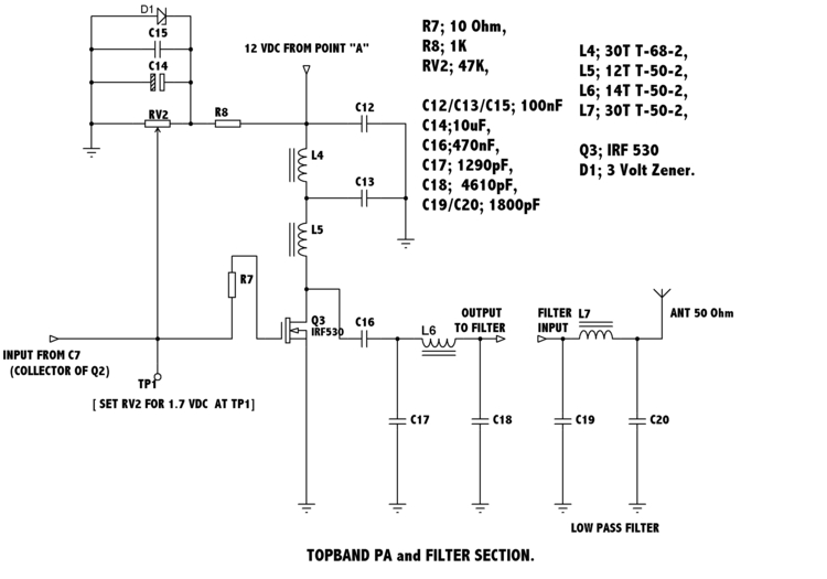
| All the above coils are wound using 22-24 SWG enamelled covered copper wire. |
| Below are the component changes necessary for converting to other bands. |
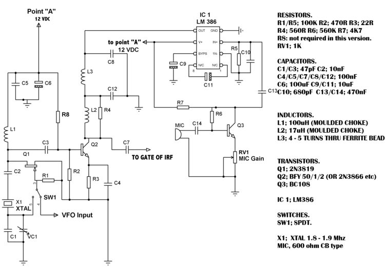
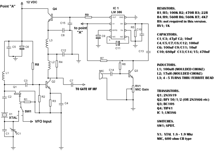
| The first part of the circuit is of the oscillator/ modulated driver stages. A LM386 audio IC is used to series modulate Q2. The LM386's output at pin 5 sits at half supply voltage and is swung plus and minus by the audio being applied to its input. In the new version Q4 allows Q2 to draw more current without damaging the LM386. The second part of the circuit is the PA and Filter sections. To set up, apply drive and adjust RV2 to give a reading of 1.7 VDC at TP1. Then by moving the turns of L6 further apart or closer together, set the RF output power to no more than 10 watts, Otherwise you will not achieve full modulation. The last thing to be adjusted is the Mic gain RV1. It should be noted that both Q2 & Q3 should have heatsinks and that Q3 should be mounted using a insulating kit. Also on bands where R8 is not needed you should not fit anything in its place, just omit the part. Provided all the components and their values are adhered to and the setting up followed, then the "Hatch" will work first time. The layout isn't too critical, some versions have been made ugly style on double sided copper clad, some on single sided and at least one on a homemade PCB. Versions for the 80 and 40 Meter bands have built and work equally well. The optional VFO can be used. But it is recomended that the circuit is first built and tested using a crystal. |
| Hold mouse over image to see original circuit. Click here to see new circuit in it's own window. |
 |
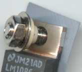 |
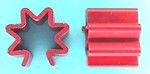
| Heatsink for Q2 |
| TO220 insulating kit for Q3 |
|
|
|