| Foekema-Kreidler 50cc-Racing | |||||||||||||||||||||||||||
| Latest update June 17, 2007 | |||||||||||||||||||||||||||
|
|
Ignition system principles | MCI Magnetic Collapse Ignition The primary coil is charged by a 12 volts power supply to establish a powerful magnetic field within the ignition coil. At the moment of ignition the primary coil current is cut and the primary magnetic field collapse. This will introduce an inductive reaction in the primary coil, as been described by the inductive law of Maxwell e = -dfi/dt. Using the law of Kirchhoff we can calculate the voltage that is being produced by the primary coil as a result of the collapsing magnetic field: u = L di/dt. The ignition coil has also a secondary coil, which has normally 100 times more windings then the primary coil. So the produced voltage, by the primary coil, is being transformed by this ratio to a very high voltage, that gives the ignition spark with a duration up to 2 milliseconds. This long burn time results in a better ignition of compressed fuel/air mixture in the combustion chamber. Therefore these ignition systems are well known to give move horsepower at low RPM. A good ignition coil has to have a large inductive factor L (henry), low primary resistance and must be able to withstand a very high voltage on the secondary coil (normally around 10,000-25,000 volts). CDI Capacitive Discharge Ignition This time the inductive voltage in the primary coil is not produced by the ignition coil itself but is produced by the ignition system. A capacitor is being charged, normally to a value of 200-400 volts, and is applied to the primary coil on the moment of ignition. As described above the winding ratio will produce the high voltage in the secondary coil and a spark is born. The advantage is that the spark length is longer then a normal MCI ignition (20,000-40,000 volts) so the engine will produce more horsepower at higher RPM as the MCI system. A disadvantage is the spark duration, it is much reduced by this method and lies between 0.1 and 0.3 milliseconds. A solution to this problem is to ignite several times, but still it isn't a continuance spark and this solution also has a big consequence for the power consumption. UltraSapI Our developed ignition system in 2002, is called UltraSap and is based of both ideas that are being described above. The core of the ignition system is based on the MCI principle, with its long duration spark to ignite the fuel/air mixture optimal for maximum power. This new MCI/CDI system is enhanced to produce a much higher spark voltage, up to 78,000 volts (4 centimeters spark length at ambient pressure). For a two cilinder engine you only need one unit, because the RPM range is up to 32,000 rpm, so more than enough for two fires in one rotation at an engine speed of 15,000rpm, like a 125cc twin racer. Another very important point in developing a race ignition system, is the moment of ignition. Because of the higher demand for more power with a wider power band, has let to the development of an ignition system that alters the moment of ignition with respect to the operating RPM of the engine crankshaft. So in stead of igniting constantly at the same piston position, relative to the sparkplug at different RPM, there is produced a delay by the ignition system. This delay results in a 27 degrees change of the crankshaft igniting position, from low RPM (1,300) up to high RPM (16,000). When the crankshaft sensor is spaced at a certain position around the crankshaft a ignition point (this will results in a pre-ignition value at a certain end RPM, here 0.83mm at 16,200 RPM) versus operating RPM is reached as shown in the Piston position vs engine RPM graph. Operating characteristics UltraSapI: Power supply: 12 volts Maximum spark voltage: 78,000 volts Minimum primary resistance: 0.9 Ohm RPM range: 1,300 - 32,000 rpm Ignition position delay: 27 degrees (from 1,300 until 16,000 RPM) UltraSapII Beacause building of an UltraSap takes many hours, it is very expensive. That is why we have designed the UltraSapII which is much cheaper. The operating is based on the MCI principle but it does even have a very strong fire and is also with a delay curve. In comparing with type I, the coil properties are more strickly and the rpm range is lower, but with 20,000rpm far enough for the fastest racing engines. Operating characteristics UltraSapII: Power supply: 12 volts Maximum spark voltage: 78,000 volts Minimum primary resistance: 1.5 Ohm (no less) RPM range: 1,300 - 20,000 rpm Ignition position delay: 27 degrees (from 1,300 until 16,000 RPM) Why ignition timedelay? Ignition time delay is only effective on highspeed twostroke engines. The forstroke engine does not need a delay but the ignitiontime has to go in the opposite way when the RPM are raising. This has to do with the reactiontime of the fuel. With a twostroke there are more important facts which are responsible for the need of an ignition timedelay by high RPM's. It has to do with the principal of the expansion exhaustpipe in combination with the temperature. If you know the pricipal of the expansion exhaustpipe, you can understand what the influance means. The expasion exhaust pipe is calculated on a certain high temperature of about 500 degrees C. But when the RPM's are raising the swap backwave needs to come earlier. So the lenght of the exhaust has to be a little shorter. But this does not work so easy, so when we are able to raise the temperature the swap backwave goes faster and that is what we are reaching when the ignitiontime comes later. This also declaires why timedelays are not effective on every twostroke engine. The engine has to work with a expansion exhaustpipe and the system is more effective with a high spread of RPM's to be used. 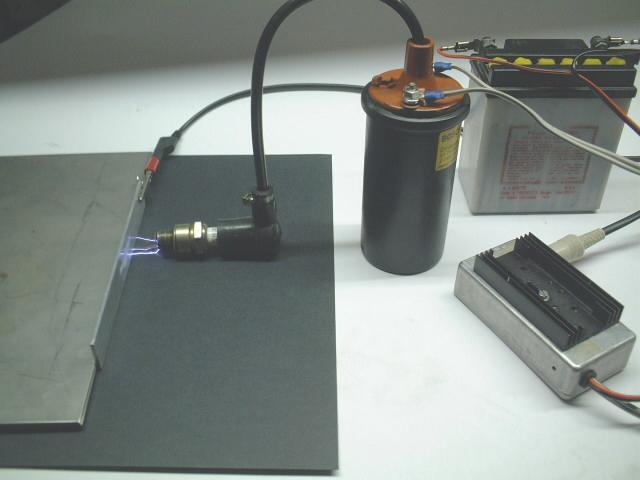 UltraSap in action 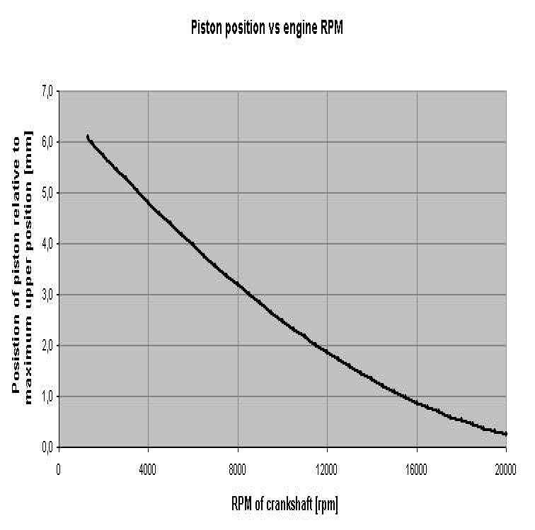 Timedelay vs RPM of the Ultra Sap Ignition system
|
|
|
If the English version is not ready, you will be automaticle passed to the Dutch version
| Home News Events Gallery Sprinting Roadracing Records Classic-Racing Technical Sponsors Links | |||||||||||||||||||||