 |
|
|
|
|
|
|
|
|
|
|
|
|
|
|
|
|
|
|
|
|
|
|
|
|
|
|
|
|
|
|
|
|
|
|
|
|
|
|
|
|
|
|
|
|
|
|
|
|
|
|
|
|
|
|
Installing the 86 Corvette Dana 44 IRS |
|
|
|
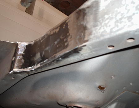
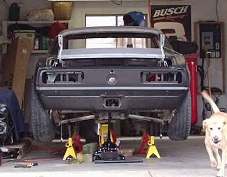
Before I could get started on the IRS install, I needed to address one of the goals of this project. 315's stuffed out back. I had done alot of internet searching and just lurking at pro-touring.com and I ended up finding some pics at DSE's website of how they do it. I printed them off and picked up the die grinder. I'd love to be able to tell you I took all sorts of measurements, but truth be told I eyeballed out a line with some masking tape where I figured I needed to cut. I based this on the pics from DSE I had taped to the side of the car. It was very close to the 3" DSE say they remove. After cutting I filled the frame with 16 ga sheet, which is what (strangely enough) the original frame is made of. Turned out well. Now with the rear quarter in place, without trimming the fender lip or rolling it yet, I have 13 in from the inside wheelwell to the fender lip. Sweet.
I haven't fabbed the tubs yet because, as you will see, I needed to have all the rear suspension in the car to be able to get a good look at exactly what needed to be packaged in/out of the tub.. Not as easy as I thought it was going to be. Am I surprised? No. |
|
|
|
 |
|
|
|
|
|
 |
|
 |
 |
|
|
|
|
 |
|
|
|
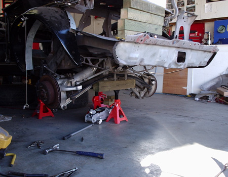
Mock Up |
|
|
|
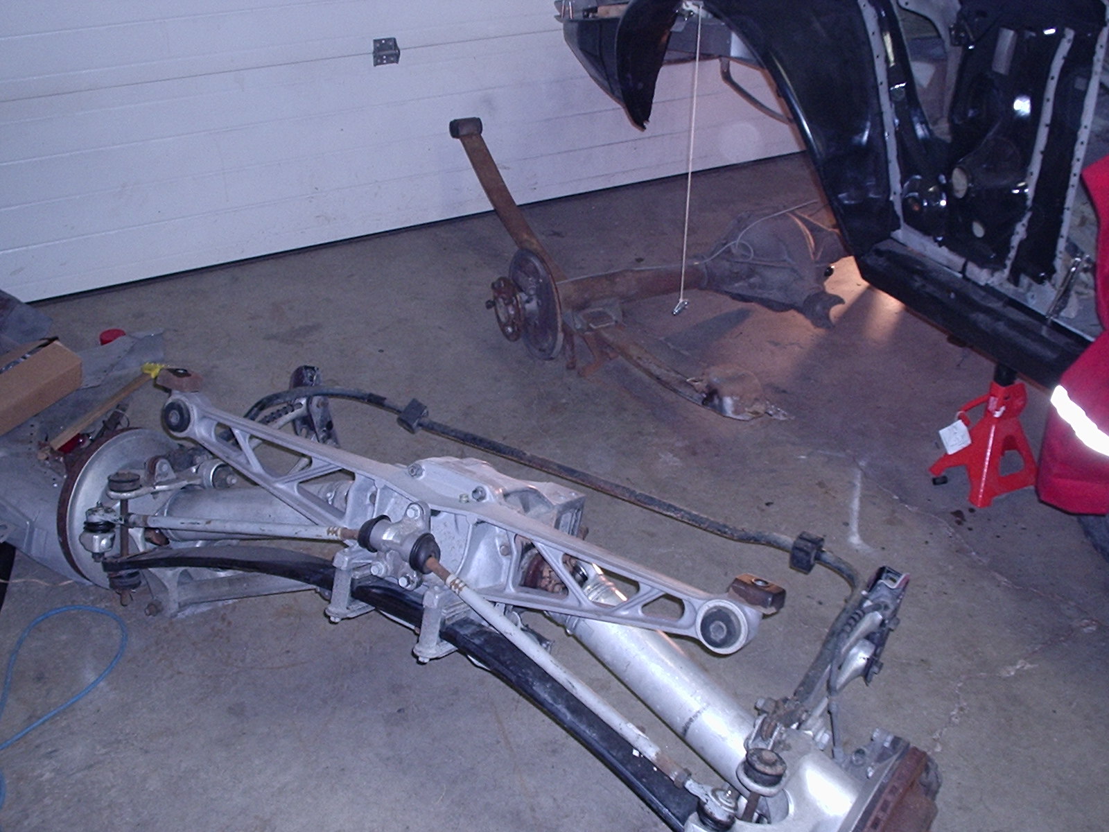
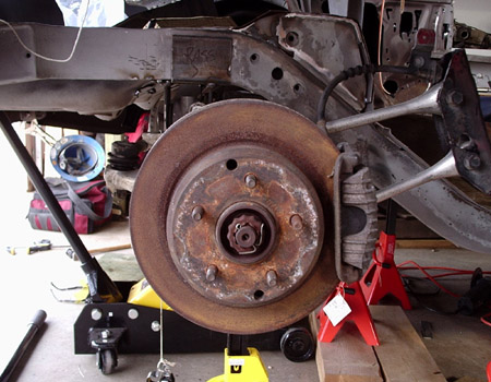
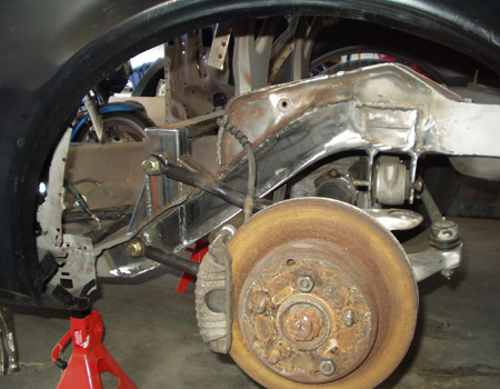
Next step was the daunting task of installing the 86 Corvette Dana 44 IRS. Keep in mind I have never fabricated anything, let alone suspension components, to this point. My dad came by ( actually drove 4 hours to my house) and we spent 2 full days getting everything mocked up as square as possible, then making templates for the crossmember brackets out of empty cereal boxes. Measure 10 time and cut once, well maybe twice. Like I said I'm new here.
It was tedious but square in the car. This was only the beginning as there are quite a few more mounting points and brackets to be fabricated at this point. |
|
|
 |
|
|
|
|
|
 |
|
|
|
|
|
|
|
 |
|
 |
|
 |
|
|
|
|
|
Crossmember Bracket |
|
|
|
 |
 |
|
 |
|
|
|
|
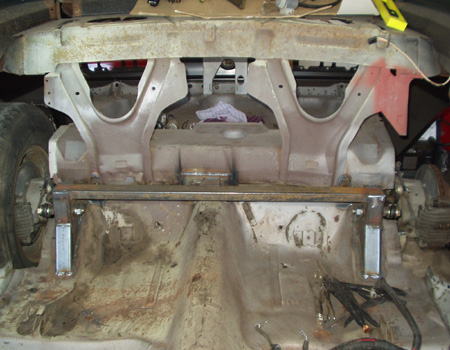
This is the simple yet effective cross member braket I fabbed up. This was fairly critical because it affected how square and true the rear sits in the car. It also basically sets the ride height. I had seen pictures on Wayne Due's website about his IRS install. Much the same as with the mini tub, I printed the pics out and used them as a guideline. In the end, the only thing close in appearence to the $700 WD kit is this bracket. Everything else I (with some professional help)ended up fabbing was done with high speed and road course abuse in mind, not just daily driving and as such is much tougher, stronger, thicker...at least in my opinion it is. Don't get me wrong, Wayne is incredibly talented and his front sub frames are one of, if not THE best going right now, and this is by no means a shot at him or his work. It just didn't do it for me personally. Nuff said. |
|
|
|
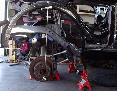
Four Bars |
|
|
|
 |
|
|
|
 |
|
|
|
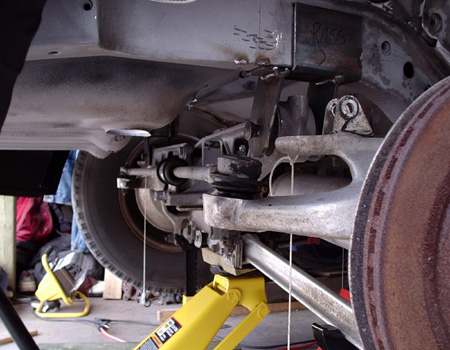
Here I'll start out with the actual bars themselves. As you can see I have chosen to ditch the factory cast aluminum bars, I have done this for several reasons. First off the goal of a 315 tire out back would have been unattainable with the factory pieces. They have dodgy rubber bushings in each end and are not able to be positioned with the kind of inward angle necessary to clear the 315's. I had originally thought about having some aluminum spacers machined with the desired angle built into one side (to point the arm toward the frame) and a flat surface on the other (to mate up cleanly to the spindle). The more I thought about it the more I realised I was trying to put a dress on a pig. No matter what, you've still got a pig. The factory arms are weak cast aluminum and the bushings are soft, mushy rubber. No good for track days.
|
|
|
|
|
|
|
|
|
The second reason I changed out the factory bars was that even if I could have got them pointing inward enough, they would have had to be mounted to some kind of spacer welded to the frame along with another set of angled milled spacers. The more I thought about it, the more Mickey Mouse the entire plan seemed. So I started from scratch. The bars shown here is what I came up with. I solved alot of the problems facing me. I can fit 315's, no problem, I have kept the factory geometry (although the bars are longer than stock, the ratio between them is identical as is the distance between upper and lower front mounting points) and the overall strength has been increased. The bars themselves are made of 1 inch DOM tubing, .250 wall. The have been drilled and tapped for the l/r fine thread of the QA1 5/8" rod ends. Overkill no doubt. All hardware is grade 8. |
|
|
 |
|
|
 |
|
 |
|
|
|
|
|
|
|
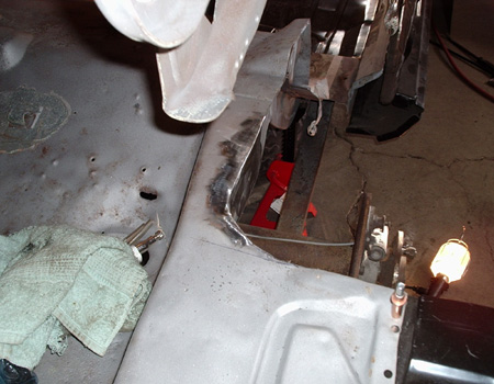
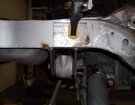
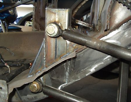
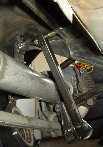
The 'tower' seen in the middle picture is something I am actually quite proud of. Turned out nicely. They are actually not just welded to the floor pan, I cut slots in the floor pan and made corresponding cuts in the tower so it would slide down around the frame rail. It turns out the framerail is exactly the same outside thickness as the .125 wall 2x4 box tubing is inside. These mounts are solid, no doubt about that. It may not sound to terribly clever to a professional, but I was bloody impressed with myself for making it work. The holes where the bolts attach the rod ends, both upper and lower, were actually drilled out to 1 inch, then I slid a 3" piece of the DOM tubing I had left over from the bars through and welded them in place. The pieces of tubing were machined out to 5/8" to accept the bolts VERY snugly. The bottom mount also has a 3/8" chunk of plate about 8 inches long welded to both sides of the frame rail with the DOM through that so the 16ga frame rail isn't taking the load. Everything fits nice and tight. You can also see the brace going across where the back seat should (will?) be. It not only ties both towers together but goes through the back wall and attaches to the beam under the car responsible for keeping the nose of the 3rd member stationary as well as being the upper coilover mounting locations. EVERYTHING is tied together. You can see the small piece of 2x1 tubing going through the back wall in the middle pic, just above and at the same angle as, the upper bar. |
|
|
|
 |
|
|
|
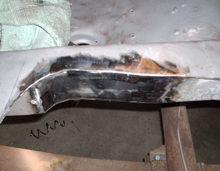
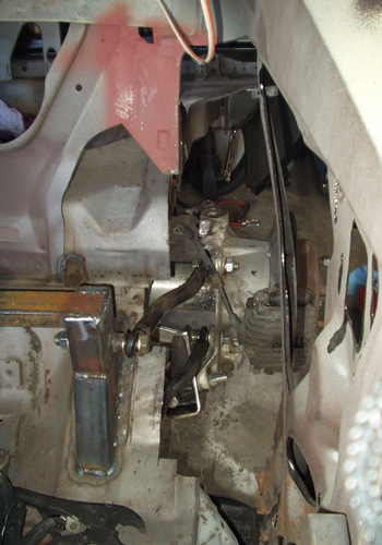
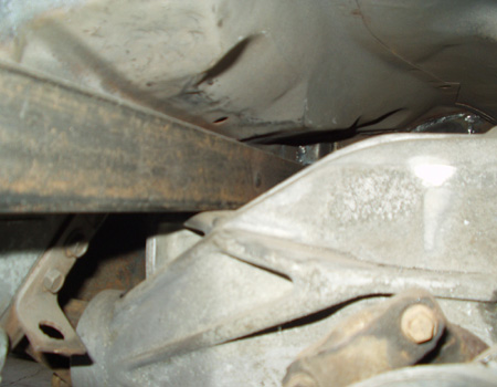
This is the support beam for the 3rd member I alluded to above. Originally this rear end had a torque arm attaching it to the tranny, because I had neither the torque arm nor the space for it this was the only option. This beam also serves as the upper mounting location for the Aldan Pro coilover's that will be suspending the rear. The photos below show that in more detail |
|
|
|
|
|
 |
|
|
|
 |
|
|
|
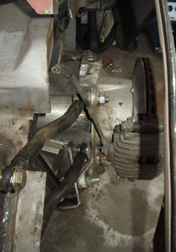
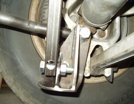
On the left you can see the upper coilover mounting location, thru the 3rd member beam. That bar is in place simply because I hadn't received the coilovers yet. Also notice how the frame has been notched for clearence for the coilover and then completely braced. This work was done by one of the fabricators at Glimmer Automotive (they installed my front subframe as well). Very nice work. I also had Glimmer fabricate the lower shock mounts. These are trickier than they look as the spindle is off camber where that bracket bolts up. Another very nice job, and as you can see very beefy. Although hard to see, the lower shock mount is bolted in 2 places to the spindle. |
|
|
|
|
|
|
|
|
|
 |
|
|
|
 |
|
|
|
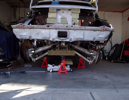
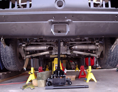
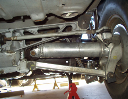
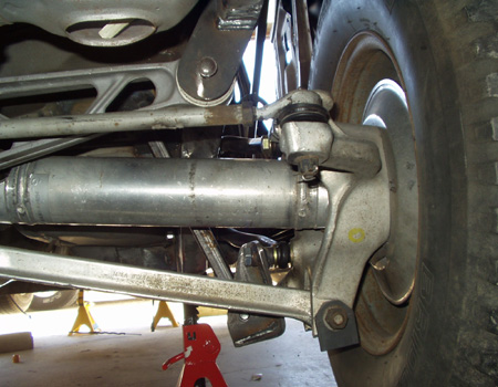
A couple more random shots |
|
|
|
|
|
|
|
|
|
Once the Aldon Pro coilovers show up, I'll install them and take some pics. You can also see the nightmare I will have with the inner wheelhouse, more on that in the futur as well. |
|