Lose those ugly signals, Use a
Turn Signal / Brake Light Integrator
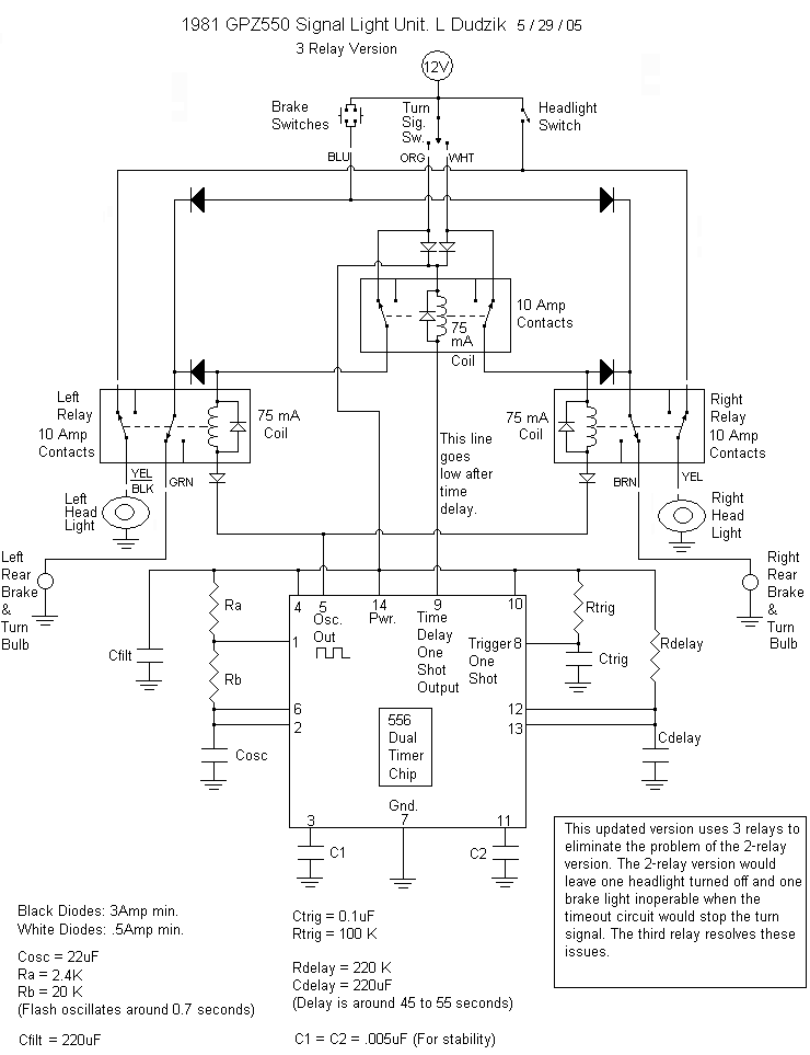
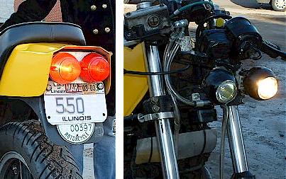
Lopping off the ugly things requires the fabrication of dual tail/brake light assemblies if your bike did not come with dual tail/brake lights. There are several circuit options once you have dual T/B lights. I chose to fabricate dual headlights as well and use them as my front signals. This requires the use of heavy duty relays for reliability and simplicity. I also incorporated an automatic cancelling timer.
One must have a fair amount of background knowledge in electronics before attempting to build one of these circuits. There is no guarantee that each of these circuits will work on every vehicle. Please feel free to Email me before attempting one of these circuits.
The circuit was designed to be cheap and simple. It was also designed with parts commonly available at Radio Shack.The relays are Radio Shack part # 275-218.
Nice sockets are available for easy replacement of the relays. part #275-220a
A 14-pin socket should be used with the 14-pin 556 chip. This helps prevent overheating while soldering.This integrator utilizes dual headlights, which double as front turn signals, and dual brake lights, which double as rear turn signals. The 556 dual-timer chip will provide the flashing oscillator and the one shot time delay. The delay is to provide a means for automatically shutting off the signal after a set amount of time.
Notes for the oscillator section:
t high = amount of time the oscillator output is high and thus the signal lights are on.
t low = amount of time the oscillator output is low and thus the signal lights are off.t high = .695(Ra+Rb)Cosc
t high = .695(2.4K+20K)22uF
t high = .34 sect low = .695(Rb)Cosc
t low = .695(20K)22uF
t low = .31 secActual frequency will slightly vary (inversely) with applied voltage.
Oscillator auto-shutoff is controlled by the Reset (pin 4).
When Reset is high, oscillator output (pin 5) oscillates.
When Reset is low, oscillator output is low.
Notes for the time delay (auto-shutoff) section:
The Delay's output (pin 9) goes high when it's trigger goes low. Then after the delay time, the output goes low (provided the trigger has gone back high before the delay time elapsed).At power-up (when a turn signal is switched on), the Trigger (pin 8) is low for an instant due to Ctrig. This begins the delay time (output pin 9 is high). The trigger quickly goes high as Ctrig charges through Rtrig. When the delay time has elapsed (Cdelay charges through Rdelay), the output (pin 9) goes low. This condition remains until power is removed (turn signal is switched off). This causes Ctrig to discharge rapidly and the entire system is ready for another power-up.
delay time = 1.1(Rdelay)Cdelay
delay time = 1.1(220K)220uF
delay time = 53 secActual delay time will vary with voltage.
The stabilizer capacitor C3 is needed to stabilize the reset signal. Without it, spikes give false shutoffs causing relay oscillations. C3 grounds the spikes.
Cfilt filters the incoming power to prevent false shutoffs.
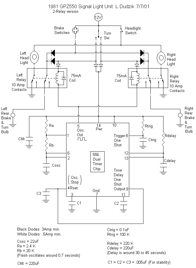
There is one anomaly to be aware of. When the auto-shutoff occurs, the rear signal/brake light will remain off. Only the other brake light will work until the turn signal switch is turned off. This is something I chose not to correct in an effort to reduce the complexity of the circuit. It can be avoided by eliminating the auto-shutoff feature. Auto-shutoff can be disabled by connecting the Reset (pin 4) to the Power (pin 14). It can also be corrected using a third relay.
Eliminating the auto-shutoff feature:
If it will be permanently disabled, some parts can be eliminated: C3, C2, Cdelay, Ctrig, Rdelay, Rtrig.
Pin 4 must connect to pin 14.
Pins 8,9,10,11,12,13 will have no connections.
Using a 555 instead of 556:
Also, if the autoshutoff will not be used, an 8-pin, 555 timer chip can be used instead. In the 555, the pinouts are different. Here is a chart for pin re-assignments:
556pins--555pins
Again, a chip-socket should be used with the 555 chip to prevent overheating while soldering.
1--------7
2--------2
3--------5
4--------4
5--------3
6--------6
7--------1
14--------8
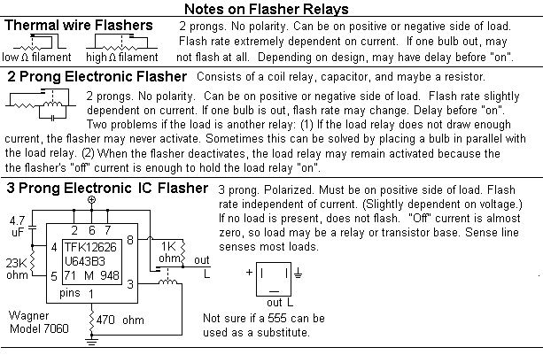
Here are some notes I had on turn signal flasher relays. They describe some of the commonly available flasher relays. For normal applications, any of the three types are useful, but the electronic ones definitely perform better than the the thermal ones. A normal application for turn signals is one large bulb at each corner of the vehicle.
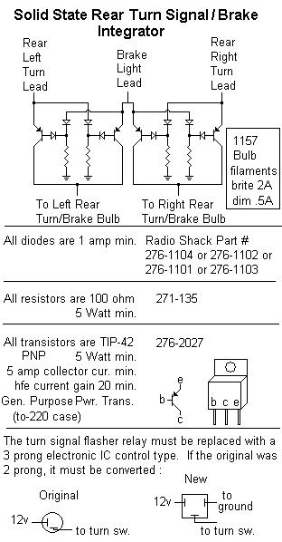
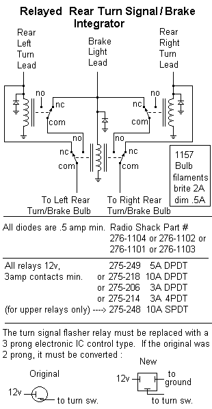
Here are two optional turn signal integrators. They both are typical integrators for dual brake lights used as turn signals.
Here is the 3-relay version of the light integrator with auto-shutoff. This eliminates the problem in the 2-relay version where one headlight remains off and one brakelight becomes non-functional after the time-out occurs and the turn signal switch remains on inadvertently.