This project is an ignition module design to replace the stock unit for a 1980 Honda CB 750 C motorcycle using aftermarket GM ignition coils commonly found on Chevy Cavaliers and many other GM cars instead of the stock coils. It also uses two GM HEI igniter modules. The parts for this project should not cost much more than $35, (not including the coils which are about $20 each). This module is designed to work with the stock inductive pickups. This project will also work as a replacement for the many other early 1980's Honda CB motorcycles that use the same pickups, rotor, as the 1980 CB 750 C. It uses a mechanical advancer unit. This project is not compatible with electronic-advance type ignitions.
Background:
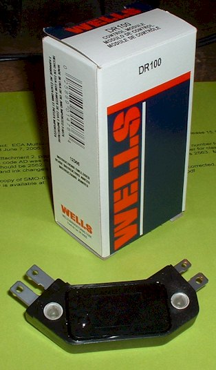
Because the CB750 has an inline, 4-cylinder engine, it requires two spark coils, two pickups, and thus, two igniter circuits. This replacement module (as well as the stock unit) actually contains two separate ignition circuits using two HEI modules acting independently. This is what the HEI modules look like:
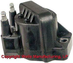
Here is what the Wells C849 coils look like.
Project:
The GM HEI ignition module is equipped with a circuit designed to increase the dwell angle to the ignition coil. However, in this application, the dwell control circuit is not needed. The Honda CB reluctor is designed to produce an increasing dwell angle, and produces enough amplitude to drive the HEI module without external DC bias. Therefore, the negative side of the pickup need only be grounded for this application. This means the W terminal will be left un-connected on the HEI module. It must be un-connected and allowed to "float", because it still affects the input signal slightly through internal coupling. Typically, in this application, W will float between .4 and 2 volts.
Results:
With the rotor gap at .6mm, the final dwell structure is as follows:
At 1000 RPM, the dwell time will be about 1.8 msec.
At 1300 RPM, the dwell time will be about 2.0 msec.
From 1500 RPM to 6000 RPM, the dwell time remains at about 1.8 or 1.9 msec.
At 8000 RPM, the dwell has reduced to about 1.5 msec.
By 10,000 RPM, the dwell time has reduced to 1.4 msec.
This is nearly ideal for the C849 coil. Excess heat dissipation in the HEI module, which occurs during current-limit mode, is minimal. At idle it is less than 1 watt. The maximum, near 6000 RPM, only reaches about 3 watts (average power dissipation). This should not be a problem as long as a decent heat sink is used on the HEI modules. (The HEI modules dissipate about 2 watts even when they are not powering a coil, so they will always be slightly warm.)
This project has the same delay characteristics as the stock ignition. (Please refer to CB ignition notes above for details on the delay characteristics.)
Startup Booster:
This project also incorporates an optional booster for use during startup. Under certain low-battery conditions, some engines may not turn over fast enough to produce an adequate pickup signal. This will prevent a spark from occurring and the engine from starting. This may require a push-start in order to turn the engine over fast enough when the battery is low. However, another solution is to wire-in a voltage booster to supplement the voltage from the pickup. This "boost" will only be in effect while the starter button is pressed.
The booster works by using the pickups as part of a voltage divider while the start button is pressed. 12 volts from the battery is applied to the diode/resistor circuit and is fed into the G terminal of the HEI module. This puts a small DC voltage on the G terminal. The pickup is about 530 ohms, and the resistor is 3900 ohms. This should result in 1.0 to 1.4 volts on the G terminal while the start button is pressed. When the pickup signal goes positive, dwell should begin. When the pickup signal goes negative, the dwell should end.
It is important to verify the resistance of the pickups in order to use the startup booster. The pickups should not be greater than about 550 ohms. If they are much greater, a larger value resistor should be used for R1 and R2.
(A 600 ohm pickup would use a 4.4K ohm resistor.)
(A 700 ohm pickup would use a 5.1K ohm resistor, etc.)
It is also important that the pickup wires do not become disconnected and the ground connection must be reliable. If these precautions are not taken, it's possible that the dwell will be infinite while the start button is pressed and there is a chance of damage to the HEI modules or even the coils.
Construction:
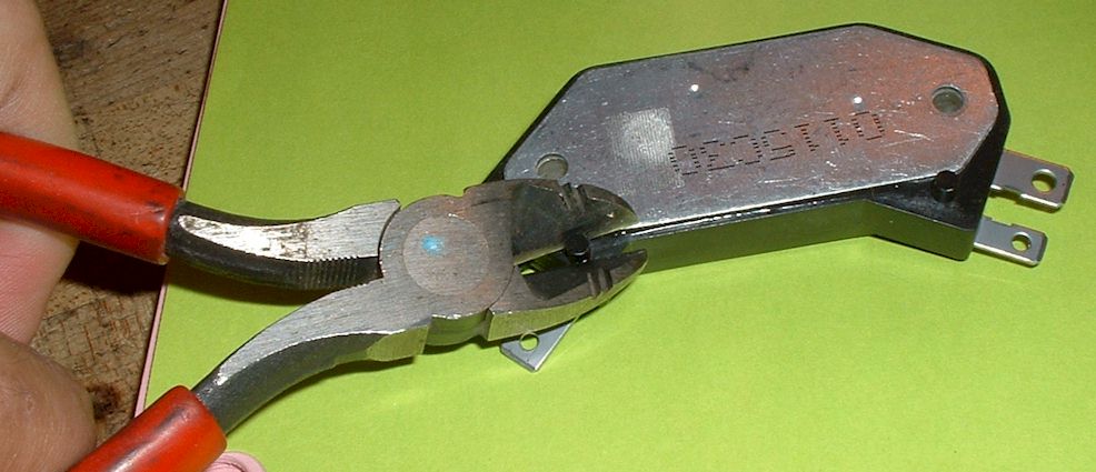
The construction of the project is simple, but first you have to clip off the two locator pins on the bottom of the modules.
Then just mount the two modules on to an aluminum plate using the supplied thermal gel and appropriate bolts. The plate needs to be at least 1/8 inch thick to be rigid. It should probably have at least about 16 square inches of surface area for adequate cooling. (It only gets slightly warm). The bolts will act as the ground connection. Next solder or use connectors to attach the wires. The parts for the startup booster should be soldered to a small board or reinforced some other way to prevent breakage from vibration and other stress.
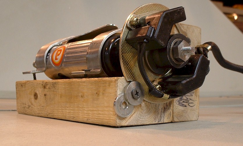
This project has been tested on a real engine and verified to work.
Here is the test rig: