Welding About Central Axis
This concept along with proper sequencing can significantly reduce unwanted distortion.
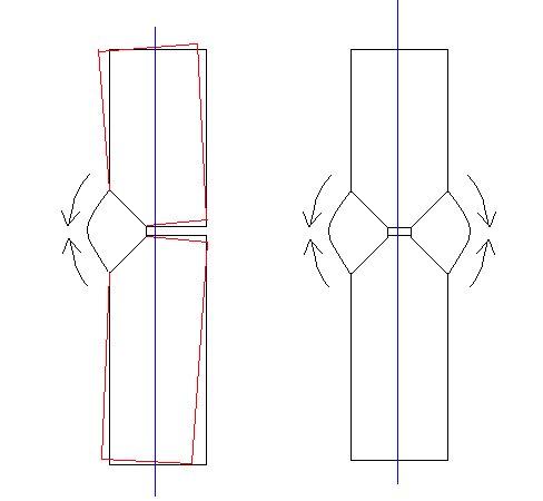
The objective is to make the shrinkage forces exert their influence against each other in order to balance out. In most cases the forces created by shrinking weld metal will act thru the central axis as a fulcrum.
The diagram shows this effect. The left side of the piece is welded which causes the shrinking force as shown by the arrows. The left side is placed under tension and stretches so that the unwelded side becomes the long side and the welded side becomes the short side.
In the example on the right the forces of the two welds balance out and the assembly remains straight. Keep in mind however that the overall length will be slightly reduced.
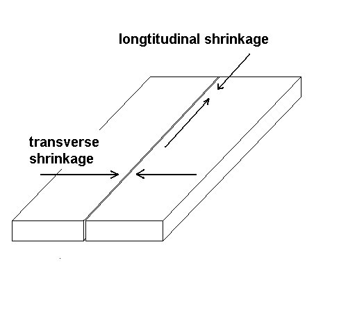
There are two main shrinkage forces that change the shape of a welded assembly as the weld cools. The transverse shrinkage is the one of main concern to most situations. When splicing plates or using long weld beads the longtitudinal shrinkage forces must also be considered.
The diagram below illustates their action. These are not the only forces that are considered by engineers but for the average application they are the primary forces.
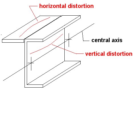
Identifying the central axis can be difficult in some applications. Generally the central axis will run through the center of gravity. If one imagines hanging the structure from a string at two single points the string will intersect the center of gravity.
A square block of metal is a simple problem that has an obvious solution . In the case of the angle iron shown the central axis is in the air between the two legs of the angle. Shrinkage from the heat of welding will act though the central axis as a fulcrum.
In the first example below the addition of a flat bar to the edge of a channel will not only pull the channel upwards but also sideways. With a three inch channel and a two inch wide flat bar welded on to the corner this bending would not be significant until the length is over two feet. One of the quick solutions is to skip weld. Often continuous welds are not required for strength.
Reinforcements added to beams can cause unwanted bending if consideration is not given to how the assembly will distort from weld shrinkage.
Often a flat bar doubler will be added to the top or bottom surface of a beam continuously welding will result in a pronounced camber. If the camber is desired the beam can be left in that condition and loading will cause it to straighten.
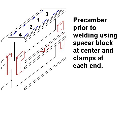
If the camber is not wanted then planning is required. The example below will cause the beam to camber. It is important to use a staggered sequence starting from the center and alternately moving towards the ends of the beam. Welding one side only will pull the beam sideways.
Removing the camber can be done two ways. The first is to weld "false" welds or heats with a torch on the opposite flange so that there is an equal shrinkage force on both flanges above and below the central axis.
The second method would be to bend the beam opposite to the direction it will distort by an amount equal to the expected distortion. The diagram illustrates this application to beams however this method can be used for any assembly that has to be welded on one side ot the central axis and distortion is expected once the welds cool.
This is not unlike prepositioning a Tee joint so that when the weld pulls the tee becomes ninety degrees.
return to index