
Indian
Flag
Tiranga
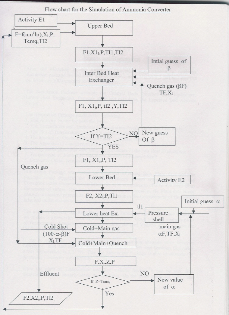
                                                        SIMULATION PROCEDURE


The Simulation of Converter was done after all the elements(viz. heat
exchangers, catalyst beds and pressure shell) were modelled and neccessary
mathematical equations were derived.

A Flow Chart(as shown below) was made to simulate the converter.The
Nomenclature for the various symbols is as follow:


F:flow rate to converter in nm3/hr.
F1:flow rate after upper catalyst bed in nm3/hr.
F2:converter effluent flow rate in nm3/hr.
Xi:mole fraction of ith component in feed.
X1i:mole fraction after 1st bed.
X2i:mole fraction after 2nd bed.
P: pressure in the converter in atms.
TF:Inlet temperature to converter in kelvin.
TI1:upper bed outlet temperature.
TI2:lower bed inlet temperature.
tI2:interbed heat exchanger tube side outlet temperature.
tl1: temperature at the inlet of lower heat exchanger shell side.
Tl1:lower bed outlet temperature.
Tl2:converter outlet temperature.
Tcmq: inlet temperature to upper bed.
greek letter alpha denotes amount of main inlet gas.
greek letter beta denotes amount of quench gas.
E1,E2:Bed Activity for the two beds.
 BACK
BACK