
Indian
Flag
Tiranga
CONVERTER
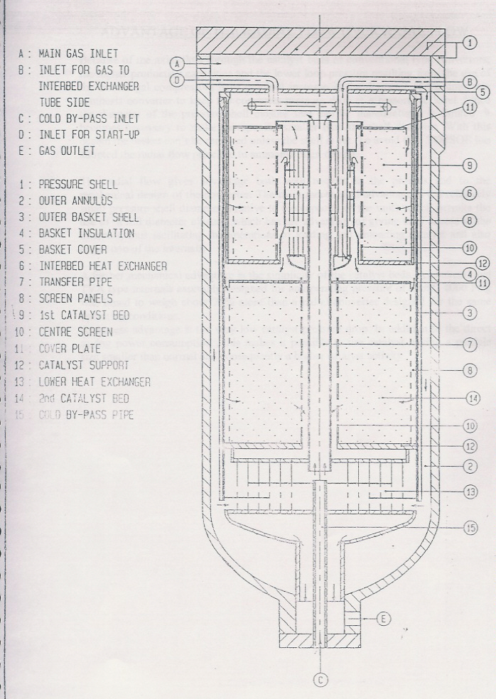
 The converter shown here is Radial Flow type.It consists of a pressure shell
with full closure and a basket with external insulation.The basket is
divided into a lower heat exchanger and a catalyst section comprising two
adiabatic catalyst beds with radial flow direction and an interbed heat
exchanger located in the center of the upper catalyst bed.
see flow diagram
 The synthesis gas is introduced into the converter in four different gas
streams. Part of the synthesis gas, designated the main inlet gas stream,
is introduced through the main inlet at the top of the converter and passes
downward through the outer annulus between the basket and the pressure
vessel thus keeping the vessel walls cooled.

 At the bottom of the converter, the main gas stream flows to the shell side of
the lower heat exchanger and is heated to the reaction temperature by heat
exchange with the converter effluents as it leaves the lower catalyst bed
through the tube side of the lower heat exchanger. At the shell side exit
of the lower heat exchanger the main feed gas stream is mixed with another
part of the synthesis gas introduced through the cold shot pipe at the
bottom of the converter, this part of the gas is designated the cold shot
gas stream. The cold shot makes it possible to obtain the correct inlet
temperature to 1st catalyst bed.

 From the lower heat exchanger the feed gas (main +cold shot) flows to the
catalyst section through the transfer pipe place in the center of the
converter. The remaining part of the synthesis gas, designated the quench
gas, is introduced through the inlet and passes through a flexible pipe
before it splits into two pipes transferring the gas to the bottom head of
the interbed heat exchanger. The quench gas passing in an upward direction
on the tube side cools the gas leaving the 1st catalyst bed to the inlet
temperature of the 2nd catalyst bed.

 The quench gas leaving the interbed heat exchanger on the tube side is mixed
with the feed gas coming from the transfer pipe. After  mixing, the gas
flows through the space above the upper catalyst bed to the annuli of the
panels around the 1st catalyst bed. From the panels it passes the 1st
catalyst bed in inward rated direction and then flows to the annulus
between the 1st catalyst bed and the interbed heat exchanger. An even gas
distribution in the catalyst bed is ensured by means of appropriate
perforations in the panels at the outer walls of the catalyst bed. The
effluent from the 1st catalyst bed passes the shell side of the interbed
heat exchanger for cooling to the proper inlet temperature for the 2nd
catalyst bed by heat exchange with gas through the tube side of the
interbed heat exchanger as described above.

 The inlet temp. of the 2nd catalyst bed is controlled by adjusting the flow
rate to the tube side of the interbed heat exchanger. From the shell side
of the interbed heat exchanger the gas is transferred to the lower catalyst
bed through the panels around the bed. In the lower catalyst bed it is
passed in the inward rated direction ,the gas distribution again being
ensured by means of appropriate perforation in the panels at the outer
walls of the bed. The gas leaving the lower catalyst bed passes the gas
having been introduced through the main inlets at the top of the converter.
From the tube side of the lower heat exchanger the gas flows to the
converter outlet.
NOTE: Information given here is sole property of HALDOR TOPSOE A/S Denmark.It
  should not be copied without HALDOR TOPSOE'S PERMISSION
BACK