![]() Mechanical
and Electrical Technology in Camp 4
Mechanical
and Electrical Technology in Camp 4
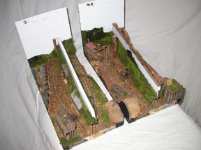
Being soo small, and built in 2 halves, Camp 4 presented many of the challenges familiar to modular layout builders, but with added wrinkles. For example, how to you wire and connect modules, when you do not have any room on the "underside" , (or the top side for that matter! ;-) ), of the module to mount wiring looms, connectors, and suchlike? How do you ensure alignment of 3 seperate tracks across the module joint, when many of the regular solutions call for protrusions which would interfer with the transport box? And as a bonus, if you can operate from both sides of the layout, how do you know which physical direction the "reversing" switch on your throttle refers to?
The technique for solving these problems was to attack them one at a time. The big issue was that once a solution was found, building it into the layout usually called for a specific sequence of assembly, so that all of the mechanical and electrical items worked together.
I should point out that while the techniques used on Camp 4 aren't "groundbreaking" in their approach, I haven't personally seen any modellers or modular layout builders use them before. (I stand to be corrected, and will happily be so). Remember, basic principles and techniques, combined with a healthy dose of "lateral thinking", can often overcome seemingly complicated and/or expensive model railroad problems.
 Firstly,
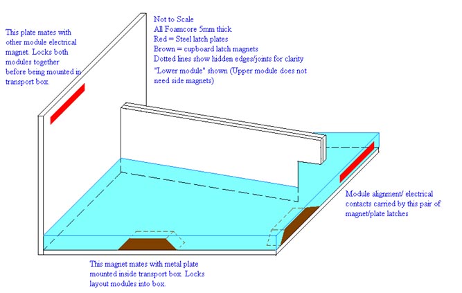
the trackplan was devised early on, and accurately plotted on the Foamcore base
sections. All of the appropriate locking magnets and steel plates were
then mounted.
Firstly,
the trackplan was devised early on, and accurately plotted on the Foamcore base
sections. All of the appropriate locking magnets and steel plates were
then mounted.
At this point, a decision was made as to which of the 2 modules would be the "lower" one. Said module recieved an extra pair of magnets, to mate with the metal plates mounted inside the transport box. This system would ensure that when inserted correctly, both modules would be firmly locked inside the transport, and would not be able to "slip" out during transport.
 Wiring
looms were then constructed, and linked to the magnet systems as required. Because
the track locations were marked, feeders could be accurately located and soldered
to the loom. When the time came to lay the extruded foam on top of the foamcore
bases, (covering the already installed main wiring looms in the process), holes
were punched, and the track feeders were inserted through them. Thus, when trackplaying,
(oops, I mean tracklaying ;-) ), time came, the feeders were already
in place, ready to be soldered to the rail.
Wiring
looms were then constructed, and linked to the magnet systems as required. Because
the track locations were marked, feeders could be accurately located and soldered
to the loom. When the time came to lay the extruded foam on top of the foamcore
bases, (covering the already installed main wiring looms in the process), holes
were punched, and the track feeders were inserted through them. Thus, when trackplaying,
(oops, I mean tracklaying ;-) ), time came, the feeders were already
in place, ready to be soldered to the rail.
 The
"upper" module required one extra item be added to the wiring loom
assembly sequence. 2 pairs of red L.E.D.s were wired up "back-to-back",
much as many throttles have as direction indicators. One L.E.D. assembly was
mounted on each side of the layout, so that it could be seen just below the
scenery edge. These lights served 2 main functions.
The
"upper" module required one extra item be added to the wiring loom
assembly sequence. 2 pairs of red L.E.D.s were wired up "back-to-back",
much as many throttles have as direction indicators. One L.E.D. assembly was
mounted on each side of the layout, so that it could be seen just below the
scenery edge. These lights served 2 main functions.
1: Even without a train on the track, they could be used to confirm if the inter-module
magnets were passing track power from the "lower" module,(which had
the power pack and throttle connections), to the "upper" module, (with
the L.E.D. indicators).
2: When a train runs through the viewblock, and appears on the "other"
side of the layout, the red L.E.D.s on the layout always confirm which direction
the train is heading.
 As
a silubrious by-product of using the magnets to pass trackpower, and assemble
the modules together for operation, the very same magnets happened to be in
the perfect position, when the "upper" module was flipped upside down
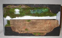
for transport, to lock the 2 modules together. Transported in this fashion,
the ends and bases provide protection for the scenic areas, even before the
transport box is slipped down over the modules.
As
a silubrious by-product of using the magnets to pass trackpower, and assemble
the modules together for operation, the very same magnets happened to be in
the perfect position, when the "upper" module was flipped upside down
for transport, to lock the 2 modules together. Transported in this fashion,
the ends and bases provide protection for the scenic areas, even before the
transport box is slipped down over the modules.
Accurate track alignment across the module joints appeared to still be a sticking point, (as it is with any multi-part layout ;-) ). However, the magnets came to the rescue again. Bearing in mind that the modules are "flatbottomed", and are designed to simply sit on a table or shelf for operation, the track level is always 25mm above the support surface. (5mm of Foamcore + 20mm of extruded foam base). So vertical alignment isn't an issue. As the track is handlaid, it was easy to mount a 10mm wide strip of Printed Circuit Board, (P.C.B) across the module joint edges, (directly above the magnet/plate sets). Each module recieved one strip of PCB, which spanned the entire 8" width of the module. The modules were assembled, and all of the track was laid in one sitting. When tracklaying was complete, the tracks crossing the joint were soldered to the PCB strips. Isolating gaps were cut in the P.C.B. to eliminate short circuits between the tracks. Then the rails were cut in-between the modules, directly aboce the module joint, with a cutoff disk in a motor-tool.
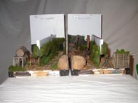
The result of the above construction details is a pair of modules which interlock together for transport. When removed from their transport case, the "upper" module is simply flipped over onto it's base, and pushed together with the "lower" module. When the magnets "click" together, a quick visual check ensures that the track "butt joints" are in horizontal alignment. Then it's plug in the power pack and throttle, put a train on the track, and let's go logging! ;-)