Locomotive Controllers -- The Power
Electronic![]() Stage
Stage
Locomotive
Controllers
-- The Power
The technical exposure of Locomotive Electronic Speed Controllers
The
following diagram shows a typical Darlington pair power stage -
this
is the standard power stage used by most British Locomotive Electronic
Speed Controllers Manufacturers. It is the standard found in just about
every
book written on Electronics for Model Railways. It is often shown
in
Roger Amos's -- Complete Book of Model Railway Electronics.
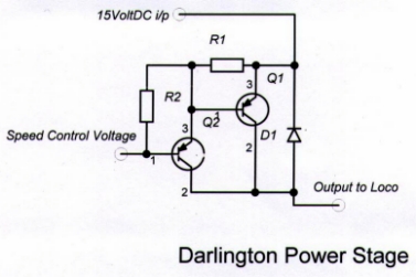
This
is very obsolete technology -- for motor speed control.
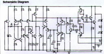
This is a fully integrated power IC -- a
one chip complex performance Power
Stage.
It
replaces the two transistor darlington power stage -- shown above.
This IC contains
25 transistors, 4 zenner diodes, 3 on chip capacitors,
and 27 resistors.
It has multi functions:-
1. It regulates the
output voltage to 0.1%.
2. It limits the
output voltage to a adjusted 0.1%. Important for Z and N
3. It has many
internal voltage, current, and phase control loops.
4. Due to the multi
tailed transistor configuration -- very low output impedance.
5. It produces a
excellent controlled voltage/current transference ratio.
This will give excellent
slow speed locomotive control. Performance a darlington
power stage cannot
possible match.
6. It will handle
1.5 Amps as a load to a 35 volt limit.
7. With external
power devices -- and subtle electronic design it will control
a 100 Amps if needed.
8. It is a smart
chip-- it will monitor its voltages, current and internal
temperature -- should
it see a short circuit on the track it will shut down electronically
very fast. It will
also shut down on over voltage and over temperature.
This provides a bullet
proof electronic system.