Getting started with the MSP430
The Texas Instruments (TI) MSP430 range of ultra-low-power micro-controllers is very comprehensive, with the little 20-pin MSP430F110/112 at the bottom end up to the 100-pin MSP430F149 at the top. The 430F110 is quite inexpensive at about $3, and samples are available free via TI's web site. It comes in two packages, the SOWB and the TSSOP. The SOWB is the easiest to work with, as it has 0.05" spacing leads. The full part number is MSP430F110IDW. It's a flash device, with 1kB and 128B of flash memory and 128B RAM. The F112 has 4kB and 256B flash and 256B of RAM.
Both the MSP430F11x device data sheet and the MSP430 User's Guide are available for download as PDF files. The latter includes all the hardware/software details of the whole MSP430 family.
IAR's development tools are available free from the TI web site (http://www.ti.com/). You will need the "Kickstart" file. The tools include a fully functional cross-assembler, CSPY, a debugger/simulator, and a C compiler. The latter is limited to relatively small programs; you have to spend quite a lot of money if you need the full compiler. ImageCraft have ported their compiler to the MSP430 and a similar offering is available from Rowley and Associates; both are very good. The excellent gcc is also available. It is free, like all GNU software, and support is available via the MSP430 gcc group.
One of the nice things about the MSP430 is that all the devices are in-circuit programmable via JTAG. They may also be debugged using the JTAG interface and the IAR CSPY tool. They can be programmed via an RS-232 link (they have built-in boot code) but JTAG programming is recommended, as it is somewhat easier. The JTAG interface (rejoicing in the name of the Flash Emulation Terminal or FET) is quite simple to make, but you are advised to buy it ready-made from Olimex in Bulgaria (http://www.olimex.com/dev). Order code is MSP430-JTAG. It's only $9.95 and the parts will probably cost you more than that if you make your own. It is plugged in to the printer port. Olimex also makes an interesting range of very cheap development boards. At only $6.95, the MSP430-H1121 is worth getting. It's a little DIL header PCB with the F112 on it, 20 pins for I/O and power, and a JTAG connector. It can be powered from the JTAG connector for programming and program execution, provided any external circuitry doesn't take too much current. It worked fine for me plugged into a solder-less breadboard. The best program to check out your hardware is fet110_1.s43, in the directory where the IAR software is installed. It's very simple, and will flash an LED connected in series with a 1k resistor to ground on P1.0 (pin 13). If you are using the F110, change the stack pointer initialization to 280h.
I've designed a little prototyping PCB for the F110/F120 that can be made at home quite easily, as it is single-sided and uses conventional through-hole components, apart from the F11x. Here is the schematic:
Here is the PCB layout, viewed from the top:
Here is a picture of the assembled prototype:
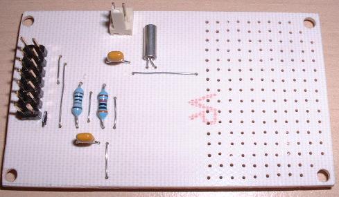
The artwork is here, in the form of a PDF file. The file is intended to be printed on tracing paper using a laser printer (ensure that the shrink/expand print options are disabled). The PCB may then be made in the usual way by placing the artwork print side down on positive-working resist-coated PCB material and exposing it to a suitable source of UV light, developing the image, etching and drilling. The larger holes are 1 mm, the smaller ones 0.8 mm.
The F11x is soldered to the underside of the board. All the other components are mounted on the top of the board. The red tracks are wire links. You will need the following components:
1 off MSP430F110IDW (or MSP430F120IDW)
1 off 2X7 way header
2 off 100nF monolithic ceramic capacitors
1 off 33K 1/4W resistor. Use 30K if you have one. It should be 30K or less according to TI, but 33K works.
1 off 100K 1/4 W resistor
32,768 Hz watch crystal (optional)
The easiest way to power the board is to use two AA or AAA cells in a suitable battery holder. Do NOT apply 5V! The board seems to work OK getting its power via the JTAG connector, although there is no explicit power connection. Being very low-power CMOS, there is enough current getting into the chip via the I/O pins for it to function. I did think of adding a couple of jumpers so this could be done properly, as on the Olimex board, but they may easily be added to the bread-boarding area, if you wish.
PCB designed with Pulsonix