
Simple LPC210x Prototyping System
The following schematic is extremely simple. It has the bare minimum for a microcontroller system based on the LPC2104/5/6 with regulated 1.8V and 3.3V supplies, reset circuit, clock and RS-232 interface for boot loading of the flash memory from a PC running the Philips LPC210x ISP utility.
If you have a JTAG interface like the Macraigor Wiggler, it is quite easy to add a 20-way connector to the prototyping area on the board and connect the pins to the appropriate signals.
Here is a PDF of the schematic, which should make the details more visible.
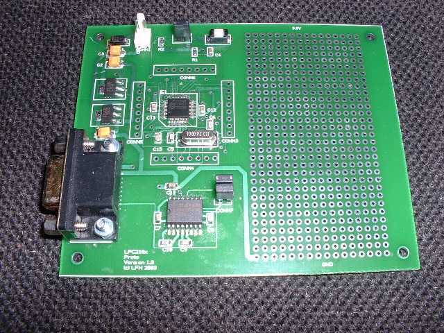
My PCB layout is below, it's double-sided to keep the cost down. I've provided a sizeable prototyping area with ground and 3.3 V supply rails.
I've had a small batch of boards made: they work very well. The Gerber and drill files are here if anyone else would like to get some made.
Here is a pic of the assembled board:
Here is the bill of materials.
I like to test hardware like this with a simple program to flash an LED. Rowley Associates has provided something like this with their latest CrossWorks ARM tools. Download a demo copy of the tools, build the LPC210x examples (Flash Debug) and use objcopy to convert the led.exe executable to an Intel hex file. You can then upload the file to my target board using the Philips ISP utility. If you want to save some time, here is the hex file. To run the program you need to remove the jumper next to the reset switch (to disable the boot loader) and press reset. You should see P0.8-P0.15 on the MCU toggling quite slowly - put a 'scope probe on their associated pads on CONN5 and CONN6. For a more exciting experience attach these points to LEDs and resistors.
Another simple test program: leddisp.zip which outputs a slow 2-bit binary down count on P0.12 and P0.13.
When you have the basic circuit working the addition of a JTAG interface for a Wiggler or equivalent will prove useful. Wire it up on the prototyping area as follows:
Note that TRST should be tied high on the LPC210x. You will also need to attach a wire to the pad on pin 27 of the MCU (DBGSEL)and connect the other end to 3.3V. It might be a good idea to use a two-way header and jumper so that the connection may be removed if not using the JTAG. DBGSEL has an internal pulldown resistor. Removing the connection will allow RS-232 booting if the Wiggler is attached.
Software development can be done on the cheap using the GNU cross-development tools. I've downloaded the latest sources and have got the compiler, assembler, linker etc. and GDB debugger working under Cygwin with WinME. The files I used were:
gcc-3.3.2.tar.gz
binutils-2.14.tar.gz.tar
gdb-6.0.tar.gz
newlib-1.11.0.tar.gz
with appropriate changes for the newer versions.
Useful links:
Philips LPC210x web page
Philips LPC2000 ARM Yahoo group
Rowley Associates: their ARM tools include support for the LPC210x.