Four-Pole Crystal Ladder Filter
This type of filter was first discussed in connection with amateur radio in English publications by Pochet in articles in Radio Communication (1976) and Wireless World (1977). I think there was an earlier article by him in the French radio society's Radio-REF.
The circuit for a four-pole filter is as follows:
All the crystals have the same value. Crystals of around 4 MHz are advisable for CW and 8 Mhz or more are better for SSB. Generally speaking, lower frequency crystals give narrower bandwidths, as do lower termination impedances. Insertion loss increases with narrower bandwidths.
The filters are quite easy to design. Coefficients for the crystals are:
k0 = 0.4142, k1 = 1.82, k2 = 2.828where k0, k1 and k2 are the coefficients for C1/C5, C2/C4 and C3, respectively.
The actual capacitances are obtained by multiplying the coefficients by 1/(2*PI*f*R) where f is in Hertz and R is the termination impedance in ohms.
For instance, doing the sums (a spreadsheet is ideal) for a filter using 4 MHz crystals with 2000 ohms input/output impedance, we get
		C1 = C5 = 8 pF
		C2 = C4 = 36 pF
		C3 = 56 pF
A SPICE simulation of this filter gave the following plot:
The 3 dB bandwidth is about 750 Hz, ideal for CW.
I've designed a PCB for this type of filter. To make it easier to approximate the design capacitance values with preferred value components, the board is laid out for two capacitors in each position. I've also made provision for broadband matching transformers using FT37 toroid cores.
The PCB layout looks like this:

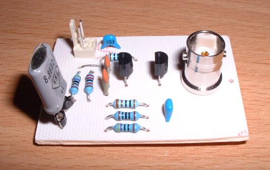
Here's a pic of the filter:
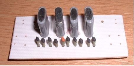
For testing purposes with resistive termination, I've left off the matching transformers. It's working as a filter, but the ripple is excessive. I'll remove the crystals and check them for frequency on the tester described below.
The best way to design these filters, if you do not have the facilities to measure the crystal parameters accurately and model them with SPICE (I'm working on a technique to calculate the bandwidth), is to prototype them first using 'ugly' construction, measure the bandwidth, ensure the passband ripple is acceptable (it should be minimal if the crystals are well-matched), and then build the filter on the PCB.
I've also designed a PCB for a simple crystal tester designed by G3PTO. This is what the PCB looks like:
I've used a couple of IC socket pins for the crystal. Here's a pic of my prototype:
The printer output files are here. Unzip it and copy the files to a LaserJet printer or equivalent. We use A4 paper in Europe so you will need to override the printer paper setting with 'Alt Continue' on the printer control panel if you get 'Load A4' in the printer display.
PCBs designed with Pulsonix .
I've had a quotation for getting a small batch of these PCBs made professionally. Price will be $8 each, including air-mail postage. Please email me for details.
73, Leon