FLYBACK GENERATORS
Flyback generators are easy to build, give impressive sparks and may reach high operating frequencies if properly designed.
The circuit below is divided in two main parts: the oscillator and the power drive.
The oscillator is built around a CMOS 4093 (4-nand gates), and configured as a pulse generator (duty cycle controled). Either on & off time may be set with the 150 kohm potentiometers (Pi/Ph). Also, the main working frequency band may be set by proper selection of the capacitor with S1. This on/off time control gives a very good regulation to fine-tune the output for maximum output voltage. (Remember that fine tunning a flyback transformer is a tricky business, internal and external capcitances usually untune the flyback; also, output mismatching).
The power drive is built around a power switching transistor (2N3055) drived by a 2N2222 which receives the command signal from the oscillator. This power transistor opens and closes many times per second the primary coil of the flyback transformer, thus inducing a high voltage in the flyback secondary.
The power transistor conducts heavy currents, so it needs a good heatsink. You may limit this high current using a current limiting resistor (ballast resistor): you may put one or two, 10ohm/10 watt resistors for this. Also it's a good idea to use some protection against overvoltages spikes in the colector, using a varistor rated at slightly less than the power transistor's Vceo (or some snubbing network to cut the spikes).
The power transistor may be replaced by a power MOSFET one (IRFs) or a IBGT, just keep in mind that the circuit should be modified accordingly, for these devices are voltage controled (and bipolar devices like the 2N3055 are current controled devices).
This model gives about 20 kv at low frequencies (5 khz) and about 5-10 kv at 50-70 khz. Depending on the flyback transformer type, power transistor and power supply you may have more than 30 watts of pure RF power!
With proper regulation and working at high frequencies, you may safely let the spark jump to your finger. Remember that although the spark it's not giving any shock you have more than 10 watts of RF power. This high frequency current usually burns tissues with great facility! RF burnings penetrate deep in the skin and take long time to heal. (In some way, with a proper electrode, you may use this generator as an electric surgical knife). The spark should jump to a metalic object on your hand and not to bare skin!
 There are many types of Flyback transformers; some have inside a high voltage rectifier (usually it cannot be removed without destroying the secondary itself), others also have a voltage multiplier stage. What we need is the old type flyback: just the hv secondary (the primary should be on the other leg and can easily be removed).
You will need to identify the return path of the HV coil (GND).
There are also auxiliary windings in the secondary side, these should be always left open! (shown as "nc" -not connected-)
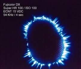 |
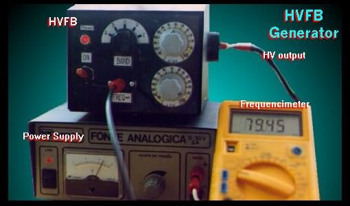
Here we have a beautiful example of this HV generator running at medium power (power supply @ 15 volts DC); the object is my fingerprint. Notice that the working frequency is about 54 kilohertz and the output voltage around 10 kv. |
 |
Here two animated gifs showing HV & HF discharges inside a lamp with no filament. |
 |