STEREO VOLUME CONTROL
by Le Magicien
 
 
A practical approach to replace those cheap stereo volume controls of almost every audio system.
Stereo Volume Control

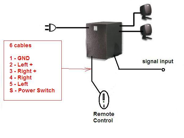
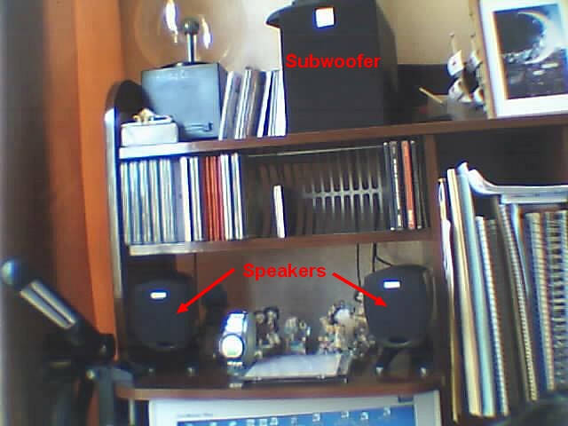
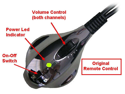
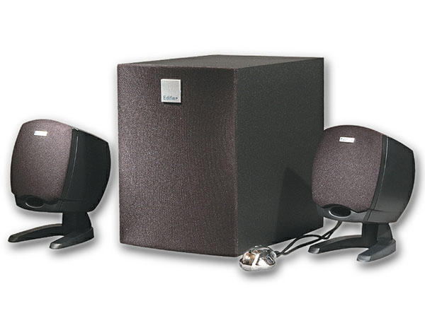
Usually multimedia speakers have a remote control for both channels like shown


But these controls wear down with an incredible speed!

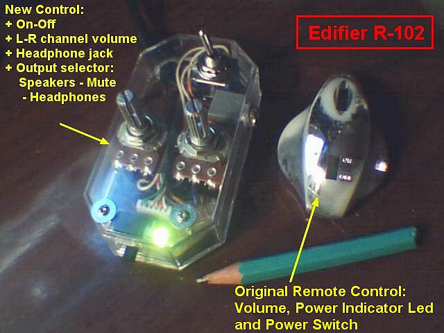
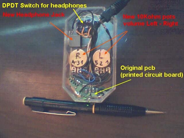
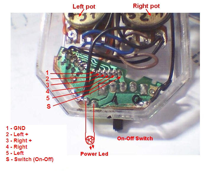
There's another problem... these potentiometers (see fig at right) are difficult to find so nothing is better than using two common pots.
 
 
One thing needed is:    the original pot value.        
Frequent values are around 10 kOhm. 
Common nomenclature for these 5  pin pots are: 103 = 10 plus 3 zeros or 10,000 ohm = 10 kOhm.


Almost every remote has three controls :
  • On-Off Switch
  • Power Indicator
  • Volume
In some cases there's a headphone jack.

Taking a closer look we'll see the that the cable between the main unit and the remote usually has 6 conductors.

The original volume potentiometer wears down very fast. The happy owner soon starts hearing scratches and channel fading.

This happens because these pots are not build for frequent use so the best solution is to replace the volume control with the common single pots found at electronic stores. 

Now these new pots, although someday will also wear down, have the advantage of being easily found and replaced!

One thing it's needed to know:    the original pot value.         Frequent values are around 10 kOhm.  Common nomenclature for these 5  pin pots are: 103 = 10 plus 3 zeros or 10,000 ohm = 10 kOhm.


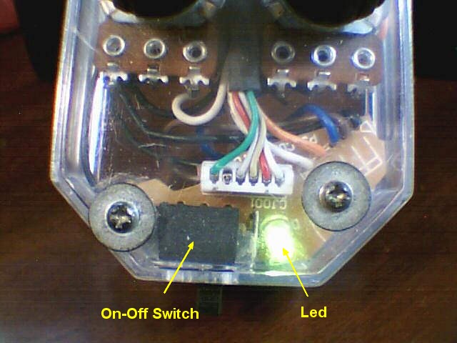
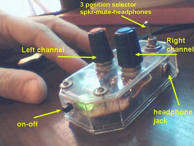
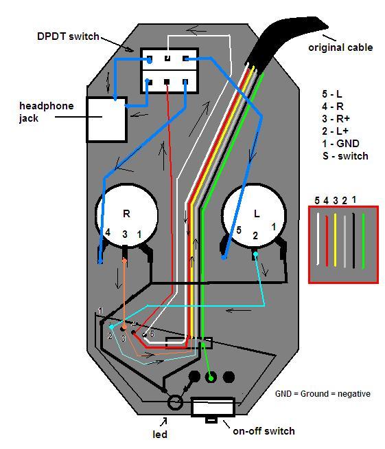
Now our project is to replace the original remote control shown at the top of this page, with a control box with two independent pots (Left and Right channels), the On-Off switch an Power Led Indicator and perhaps an output for headphones with the proper 3 way switch - DPDT - (Double Pole Double Throw - Center Off).


The first thing needed is a practical box for housing the new project.


I had these handy clear plastic boxes from refilled inkjet cartridges.


Compare the size of the original remote control (on the right side of the photo) with the new box housing the new pots, left and right channels.

Note that the original printed circuit board was salvaged from the original remote  thus there is no need for new parts!

The original on-off switch, power led indicator and cable connectors were all on the pcb which need only a little bit of trimming in order to fit the new box.


In this view from below, the original cable entering the remote is shown in the upper right corner.

Note the original pcb, trimmed to fit the box.


This schematic shows the general arrangement of wires.

Before entering the pots, Left and Right signals (5 & 4) go to the DPDT (Double pole, Double Throw) switch. From there it may go directly to the headphone jack or to the pots.

Attenuated signals form the pots (L & R), pins #3 and #2 now are outputs that must return to the main circuit box, thus re-entering the original cable.

Please note the arrows' directions! (inputs & outputs)


Salvaged pcb from above.

Note the original White connector entering the pcb.


Detailed view of the pcb from below.


The final result, a nice control box, very ergonomic and most of all:

PRACTICAL!!!


The satellite speakers were originally designed to rest on a table but...  in my case they are located just above the line of sight...


As said before, the original base is tilted upwards, In my case this is bad for the sound must go below the plane were the satellites are located.


The most simple solution is to change the speaker inclination, which is done by a cardboard inserted at the rear side of the base... :-)


A cardboard tongue is fitted inside the support , it's not glued! Just pressure inserted!


any questions?  just send an e-mail!  [email protected]


Feb 2007

Le Magicien

Home Page
1