
1.5 Volt Strobo with a
Kodak Max Disposable Camera
by Le Magicien
This articles shows how to modify the flash circuit that comes with a cheap Kodak Max Disposable Camera in order to use it as a low frequency strobe.

These cameras are disposable, which means that photoprocessing labs throw them away after film extraction, so you have for free these useful and totally functional flash circuits for your projects !!! (sometimes they dispose the cameras with the 1.5 volt alkaline battery inside).
Inside this camera there is this handy flash unit which we were talking about; the nice thing is it works on a 1.5 volt alkaline battery, what makes this circuit very useful in a variety of low power application. So next time ask the processing lab if they can keep the disposable cameras for you !!!
OPENING THE CAMERA
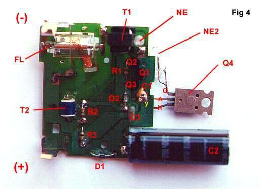
With the camera opened you'll find a circuit board very similar to the photographs shown below; carefully, remove the circuit from the camera while taking note of battery polarity and shutter metallic contacts (these contact will close during the exposition in order to trigger the flash).
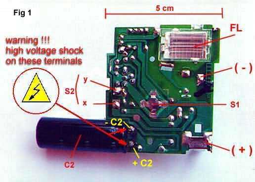
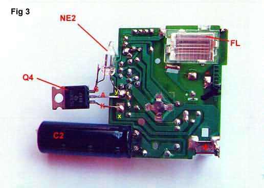
FL : Flash Lamp with reflector and protection lid
S1 : Charge Start button
(+) (-) : 1.5 volt alkaline battery contacts
C2 : 160 uF/350 volt electrolytic capacitor
S2 : shutter contacts - triggers flash when terminals x and y are short-circuited
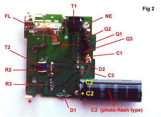
T1 : Step up transformer (1.5/350 ratio apron)
T2 : Trigger coil - HV trigger to ignite FL
NE : Neon Lamp (turns on when C2 is charged- flash charge indicator light)
T2 : Trigger coil - HV trigger to ignite FL
for other components see circuit diagram below
After some "reverse engineering" I came with the following circuit for the flash board. Please note that this unit has no SMD components, but I've found newer cameras with them, but the circuit is essentially the same.
I need to desolder D1 and D2 in order to properly identify these components, also need to take a closer look to Q1 transistor type (base bias resistors included inside the transistor case???).
THE STROBO - Circuit Modifications
As I didn't have a SIDAC device with me (it triggers when voltage between terminals reaches certain value), I used a SCR and a neon lamp to improvise one, not a perfect solution but it works well.
As you may see between trigger terminals
x and
y of
S2 I've put a
SCR (TIC 106M) which is triggered when the voltage between
NE2 terminals reaches certain value (aproximately 200 vdc). This means
NE2 is a neon lamp of 200 volts or so (note in fig 3 the wide gap between electrodes inside the neon lamp).
The modified circuits is shown below:
Notes
Note that different type of neon lamps used in NE2 will give different triggering voltages, in many cases a value too low will not let the main capacitor C2 to acquire a full charge, perhaps producing no flash at all!!! I used a neon lamp of 200 volts which, I know, is not an easy-to- find component, but it may be replaced by two or three common NE lamps of 60-80 volts each, wired in series, in order to reach 200 volts or so.
WARNING: ALSO REMEMBER THAT THE MAIN CAPACITOR C2 (THE BIG ONE) HAS A NICE CHARGE STORED INSIDE, IF YOU ACCIDENTALLY SHORT-CIRCUIT ITS TERMINALS WITH YOUR BODY, YOU'LL RECEIVE A VERY NASTY SHOCK !!! (watch your underwear!!!) Be sure to short circuit C2 terminals with a screwdriver before circuit handling !
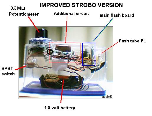
IMPROVED STROBO VERSION- Circuit Modifications
This new version is based on an electronic schematic given in the topic
"Converting a Pocket Camera Strobe into a Repeating Strobe" from the wonderful Sam's Strobe FAQ page (located at http://www.misty.com/people/don/samflash.html#strbcpp).
The values given in the additional circuit are the actual ones of the working prototype (I used what I had at the moment), but certainly they may be altered without affecting the overall performance.
- Mark on the circuit the negative (-) and positive (+) terminals of capacitor C2, as seen in Figs 1 & 2.
- The original capacitor C2 (photoflash type - usually 120 to 160 microfarads, big black cilinder in Figs 1 to 4) must be removed.
- The additional circuit -ADCIRC-(see schematic below) will have 3 connecting terminals: Z1, Z2 and x.
- Terminal Z1 of ADCIRC will be connected to -C2 terminal of camera flash circuit board; terminal Z2 to +C2 terminal and 'x' terminal of ADCIRC to the 'x' terminal of S2 as shown in Fig1.
- The 3 megohm potentiometer in the ADCIRC controls the frequency of the flashes, from a dozen hertz to few flashes per minute.
- Finally, short-circuit switch S1 shown in Fig 1 (solder a wire between S1 terminals).
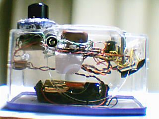
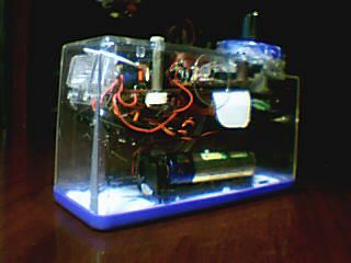
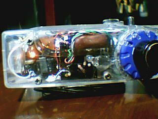
In order to integrate the two circuits into a single unit, I decide to use the clear plastic box inside which some "submarine disposable cameras" come.
Here's a photo of how neat things were arranged inside!
Last Review
by LeMagicien
June 3, 2005
