This is the project of a Light Chaser robot. The robot will turn towards the brightest light and move forward chasing or following it. It has two motors (left & right) in order to make the turns; on top two light sensors (photodiodes) separated by a PC board in order to simulate "a nose". This nose is particularly important because it will provide a shadow thus preventing both sensors from being illuminated when a side light is present (the motor on the non-illuminated sensor side will turn on thus aiming the robot towards the light). When the light is right in front of the sensors, there will be no shadow and both sensors will be equally illuminated, i.e.: both motors will be running and the robot will move forward.
The main robot board was an old MOVIT kit, it had two IR pairs of sensors (emitter-receptor) to read a rotating cardboard circle painted black and white in two circumferences. This sequence of black and white sectors programmed the robot to make turns, move forward, stop, etc. This part of the circuit was removed and a new circuit was designed and put in place
Click on the left to see the main circuit of the Light Chaser.
CONSTRUCTION, CIRCUIT DESCRIPTION and PHOTOGRAPHS
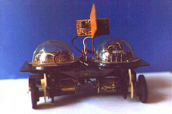
Here on the left we see the front view of the robot, the right plastic dome has inside the original circuit for motor control. The one on the left has the new circuit.
Right in the middle, a pair of photodiodes separated by a PC board "nose"; this circuit is supported and held in place by a rigid wire bent to put the sensors in the best position.
Below the main platform we see the motors and the gearboxes.
Originally there was a third motor to rotate the cardboard disk I've mentioned above, this motor was taken because it has no use in the new circuit.
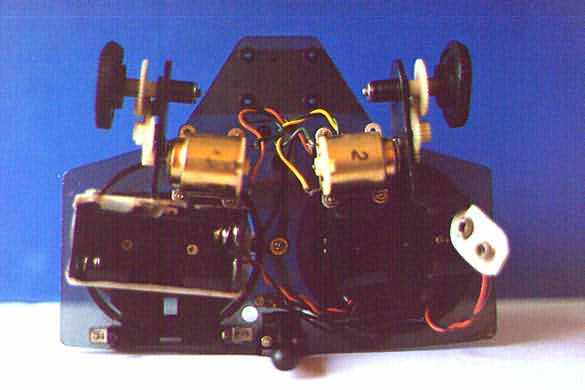
Here on the left we see the lower part of the platform: left & right motors with its gear boxes, battery holders (3 volt for the motors and 9 volts for the control circuit).
Right between the batt holders we see a support terminated in a plastic sphere, although I could replace this 3rd support, if the surface is smooth enough the robot will move without any problem, only in rough surfaces this support should be replaced by a pivoting wheel.
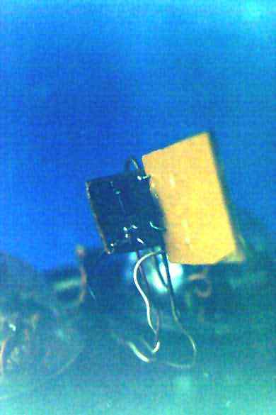
Here on the left you may click the photograph to see a more detailed view. This one shows the right photo sensor with the PC board acting as a "nose".
Now the general connections schematic, as you see the original circuit was preserved, only the Added Sensors Circuit & Sensors (RFT / LFT) are new.
Motor connections to the original circuit are preserved, but now we have SR and SL going to the Added Circuit, and the connections to the photodiodes RFT and LFT
Also we need a +9 volt / GND supply to the new circuit and sensors.
This is the basic arrangement of the Added Circuit without the sensors that go at the RFT and LFT pins.
As before, SR and SL command logic signals go to the main circuit board (Original).
ABOUT THE CIRCUIT
Here's there's no big deal. See the main circuit in a new window click here,
while you continue reading this description (you may call the new window every time it's needed).
The basic circuit is a MN 4584 - CMOS HEX Schmitt Trigger Inverter and some additional components to control both motors. Although this IC has 6 gates, only 2 are used. You may replace any of these gates using a 4093 CMOS as suggested in the main circuit schematic. Japanese transistors 2SC945 may be replaced by any NPN 100 mA/50v unit like BC548 or 2N3094. The 2SC2120 units may be replaced by any 800 mA /35v component, like BC337 or 2N2222.
The command control signal from the Added circuit enter the Original circuit by pins SR and SL and go to potentiometers P1 and P2. This potentiometers set the response threshold level upon which the 4584 CMOS gate will actuate.
If SL (or SL, or both) are high, we may regulate P1 so as to obtain a low output from the 4584 gate. Being the output in low state, the 2SC945 NPN transistor is off and as the base of the 2SC2120 is connected to ground by a 1 kohm resistor, this last one is also in off state, therefore the motor is stopped.
On the contrary, if the command signal SR is low we will have a high output from the gate which in turn will drive the 2SC945 through the 4.7/10 kohm voltage divisor to an on state. Now the base of the 2SC2120 has a positive supply and turns on, running the motor.
Here you have the photodiodes RFT or LFT connected to the base of a pair of PNP transistors in darlington configuration.
When the photodiode conducts due to incident light, the base of the PNP goes toward ground thus both transistors conduct heavily. The emitter goes toward ground and the resultant SR signal goes toward O volt.
If the situation is reversed, the less illumination upon the sensor, the higher the voltage at the base (referred to gnd) and the less the PNP pair conduct, the command SR signal will go toward + 9 volt now.
Put the robot on a support so as the motors may turn freely, (you don't want to chase the unit while calibrating!). Illuminate both sensors with a flashlight (make sure both sensors are getting the same illumination!!!). Slowly adjust P1 and P2 until both motors are turning at the same speed.
You may also adjust the point at which you want the motors to turn on, i.e.: how much light is necessary to actuate the motors...
Put the robot on the floor, point a flashlight toward the sensors. If both sensors are illuminated, the Light Chaser will run straight at the flaslight (means you!!); if not, it will start turning towards the flashlight until both sensors are equally illuminated, then it will stop turning and advance straight towards the light source...
After some experimenting you may easily make the light chaser keep following you as long as you keep both eyes illuminated with your flashlight... (just a kind of electronic pet that follows the owner).
Another experiment is performed during the day, with a window open letting sunshine come inside the room; the light chaser will run towards the window "hungry for some sun"...