Wavelength determination using a diffraction grating from an inkjet printer (HP600series)
From an old inkjet printer (HP 600 series) I took the optical positioning ribbon which is nothing more than a series of very closely spaced black vertical lines over a transparent tape thus giving a beautiful diffraction grating.
What I needed was to calculate precisely the distance between these lines...

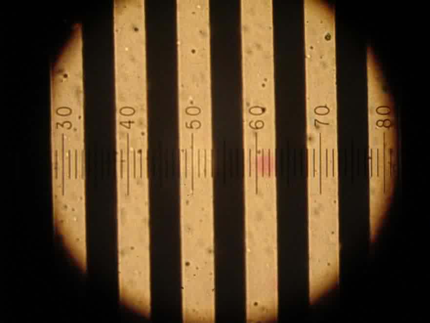
In order to calculate this distances I used my dad's microscope. Although it's a 70 years old unit, it's in good working condition, Zeiss optics and millimetric focusing system. The most important thing was that along with the microscope was a micrometric eyepiece! one with 0-100 divisions engraved on it.
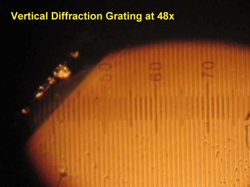
What I needed was to calibrate the scale. after several measures in order o lower error figures, was established that at 48X, each division in the micrometric eyepiece was approximately 17.4 micrometers (um).
Now, with this constant, I put the printer ribbon on the microscope and observed that approximately 10 lines took 97 ocular divisions. Thus, 9.7 divisions between grating black lines, and, as 1 div=14.7 um we have,
9.7 div x 17.4 um/div = 169 (um) micrometers. Cool!
Here we see a little piece of the diffraction grating - printer's optical positioning tape- on the microscope stage.
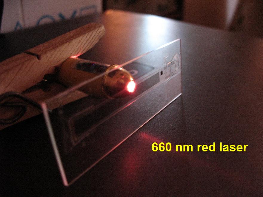
Now all I had to do was setting the grating at the head of the laser, measure the diffraction pattern and the distance between the laser and the screen. This distance should be as longer as possible!
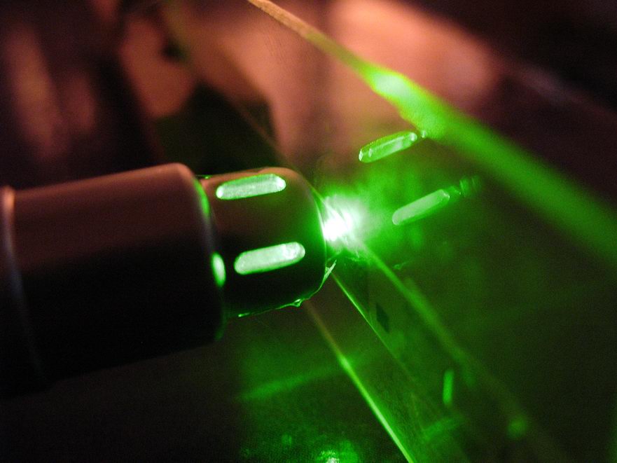
Green laser pointer (8 mWatt) and the diffraction grating attached to a microscopic slide with some adhesive tape.
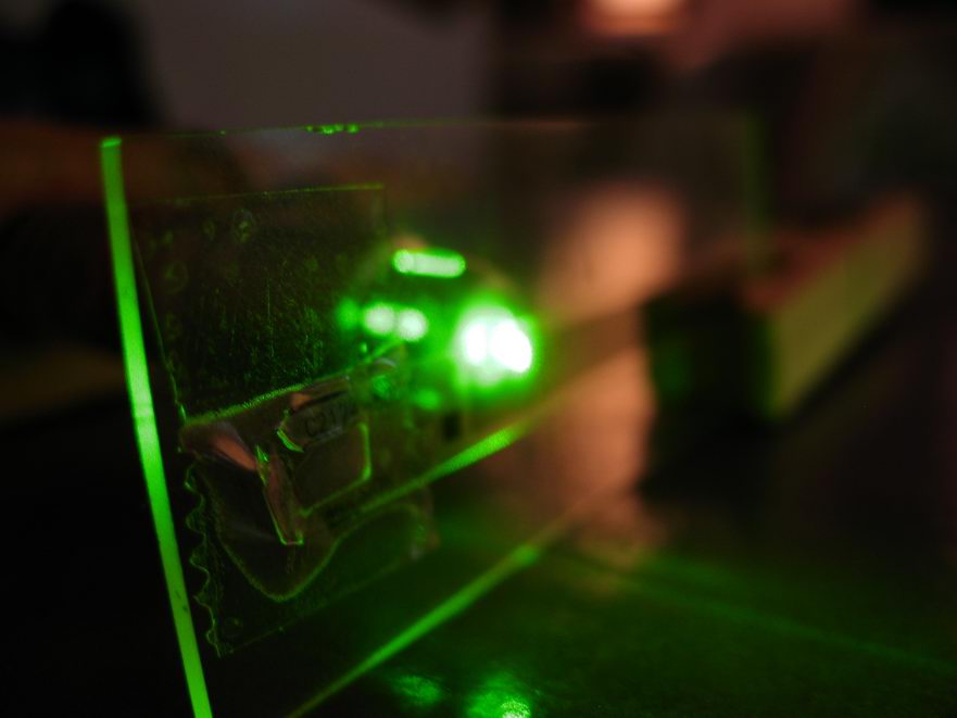
Another view of the diffraction grating and laser pointer.
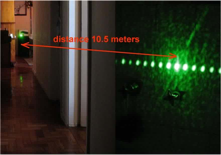
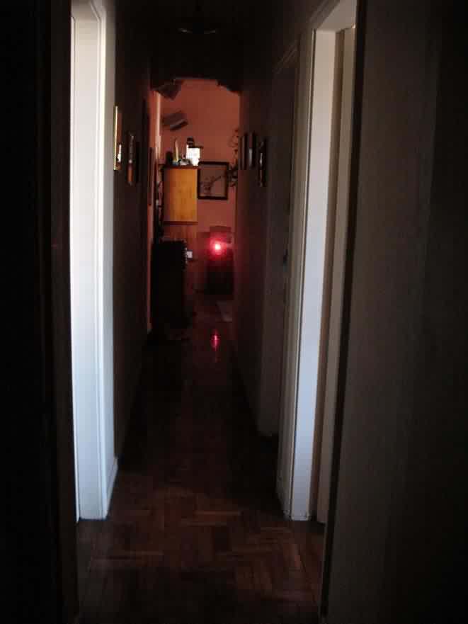
Looking for the longest distance available at home, I found the corridor was the best choice. From the living room wall (left side on the picture) to the bathroom wall (right side on the picture) there was 10.5 meters.
On the left side of the following photo composition the diffraction pattern projected over the bathroom wall
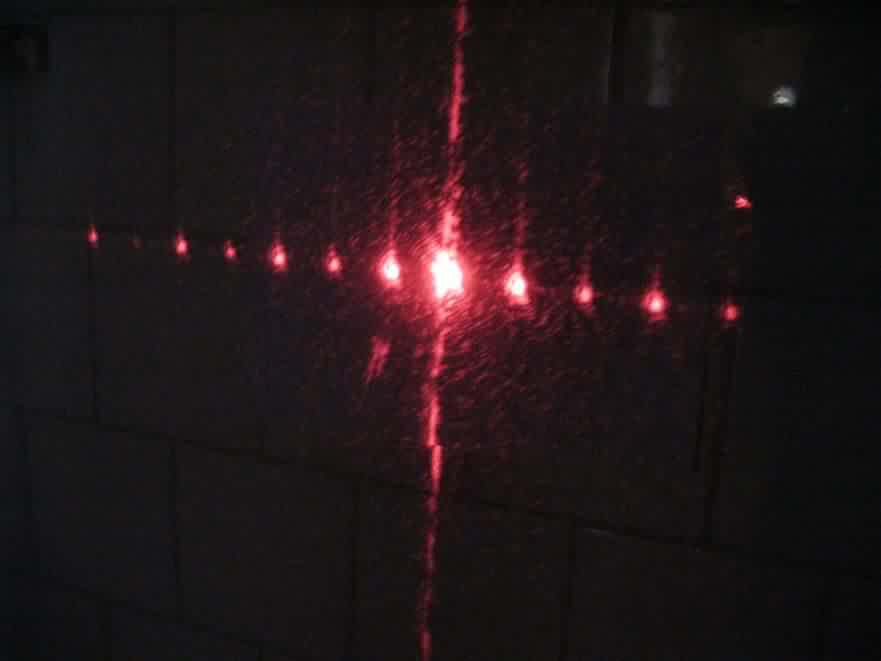
Now an image of the diffraction pattern obtained. Distances from central maximum to 1st, 2nd and 3rd maximum are given.
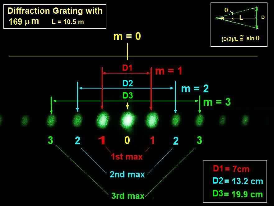
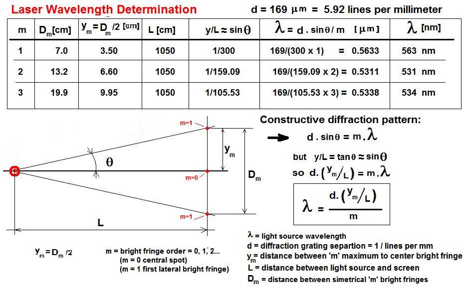
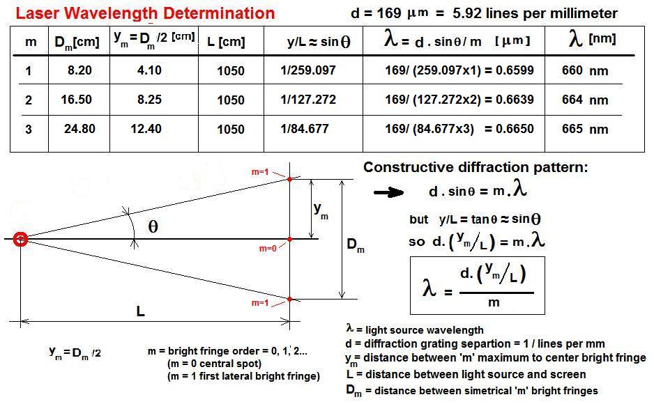
With all data in hand the following table shows how to calculate the wavelength of the laser light going through the diffraction pattern according the distance between the central maximum and the 1st, 2nd and 3rd ones.
Note that as we increase the distance from the central maximum (m=0) the calculation improves, giving a figure of 532 nanometers. Not bad for a home made bench experiment!!!
This 532nm figure is the same that's on the laser pointer label...
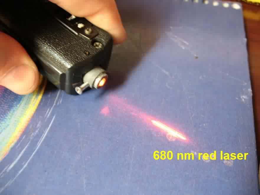
Same arrangement as before but this time with a red laser. It should give a wavelength figure around 640 nanometers
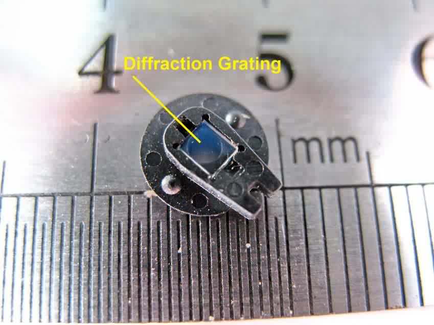
DVD Diffraction Gratings
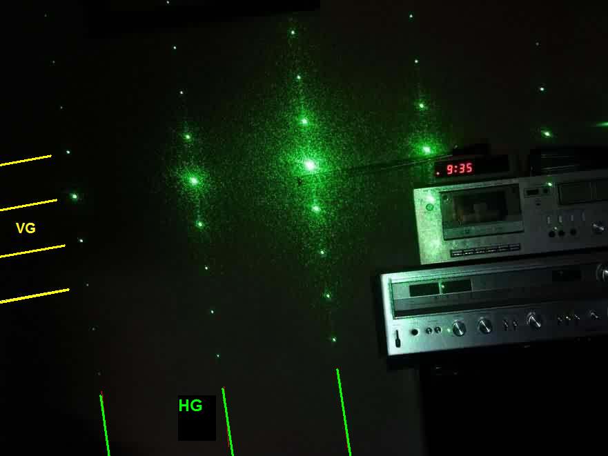
This one has two diffraction grating perpendicular to each other and its resultant diffraction pattern is an amazing one!!!!
In this case the gratins are engraved on a very small crystal slab which was taken from a DVD computer drive head.
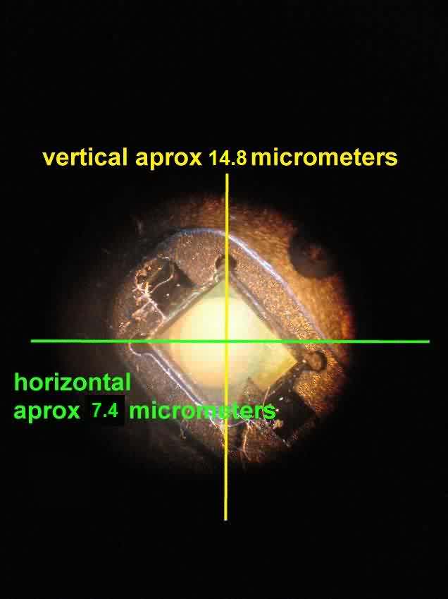
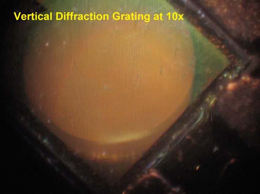
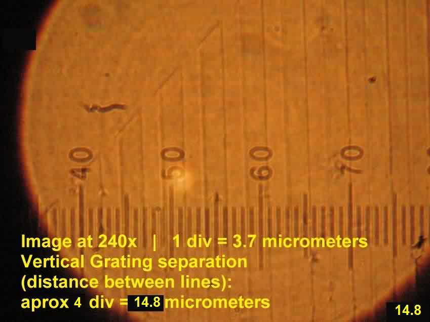
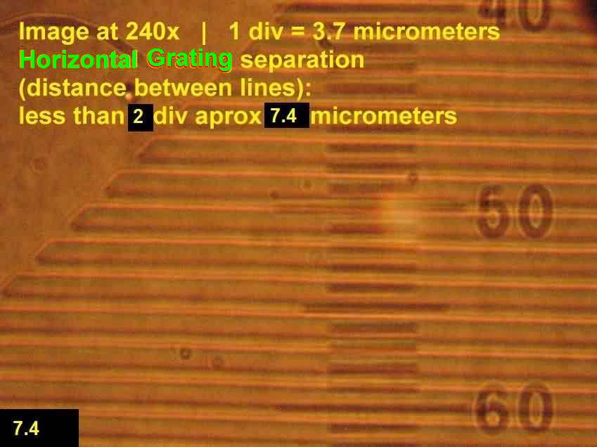
It has two perpendicular gratings, one with approximately 14.8 micrometers (um) which we call the Vertical Grating (shown by a yellow line) and the other with 7.4 um called Horizontal Grating (shown by a light green line).
This values were obtained using a microscope equipped with a micrometric ocular (eyepiece).
Next images will show how it was done
Green Laser pointer (8mWatt unit) with the attached diffraction grating .
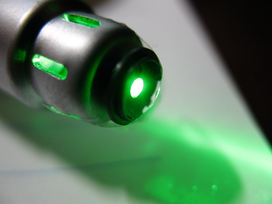
Image of the double diffraction grating using the green laser pointer... pure beauty!
Remembering the formula for interference maximum and minimums
y = L . wl / dg
where
y = distance of bright spots (maximum) to the center one.
L = length from the diffraction grating to the screen.
wl = laser wavelength
dg = diffraction grating constant, i.e.: distance between grating lines.
from this formula we conclude:
That the distance (y) between bright spots (maximum) to the central one (m=0) it's the reciprocal to the distance (dg) between the lines of each diffraction grating. Gratings with closer lines give diffractions patterns with wide spaced points.
Analyzing the diffraction pattern in following image it's clear that:
the diffraction grating with closer spaced divisions (HG / 7.4 um) gives a diffraction pattern with the bright spots widely spaced. These are the horizontal points. So the horizontal bright spots are produced by the Horizontal Grating(shown by light green lines) which in this experiment is in vertical position.
Inversely,
the diffraction grating with widely spaced divisions (VG / 14.8 um) gives a diffraction pattern with the bright spots closely spaced. These are the vertical points. So the vertical bright spots are produced by the Vertical Grating(shown by yellow lines) which in this experiment is in horizontal position.