This is the project of infrared vision system for a toy car. It will project 2 modulated IR beams ahead and detect any reflection of these beams on any obstacle ahead of the car. The circuit will then invert the car's motor for a given time thus changing the direction of advance as it goes in reverse. No special control for steering is necessary as the car has the front wheels' shaft in an eccentric support: when going forward it autoaligns itself, when running backwards the shaft turns and the car describes a curve.
Click on the left to see the main circuit of the Infra Red Vision System.
CONSTRUCTION, CIRCUIT DESCRIPTION and PHOTOGRAPHS
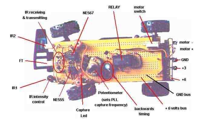
The main circuit given above is mounted on a PC board that will be fixed over the car. Ahead and on the sides we'll put the IR emitting diodes (2), in the center, the IR reception phototransistor FT. Also the capture frequency potentiometer for easy adjust is located above, on the PC board.
The original toy had a wireless remote control unit transmitter with only 1 channel, backwards. The car normally runs forward but upon signal reception the car's circuit inverts the motor polarity and the car runs backwards. As shown in Fig 1, the front wheel shaft is fixed at an eccentric point S in relation with car's centerline. When the car is reversing, the front shaft also turns due to the different friction torque acting on point S, therefore turning the vehicle.
This mechanical construction is particularly practical when we have only one radio channel available to control de car.
In our project we will cannibalize the car: the reception circuit won't be used, only the 4x1.5 volt AA cell holder and the motor (3vdc) will remain. Also, the wireless 1 channel remote control won't be used.
The car's battery holder will be modify in order to have: +6 volt, +3 volt and ground. A switch may be used to prevent the motor from running: this is an important feature when calibrating and alineating the sensors...
The circuit will be mounted according to the following photographs.
Note how nicely the PC board fits over the car.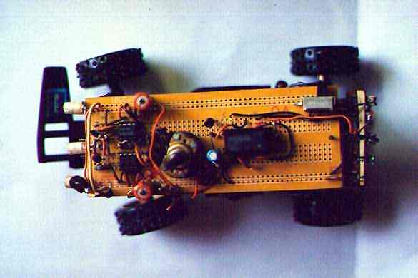 |
The PC board must have a length slightly less than the car.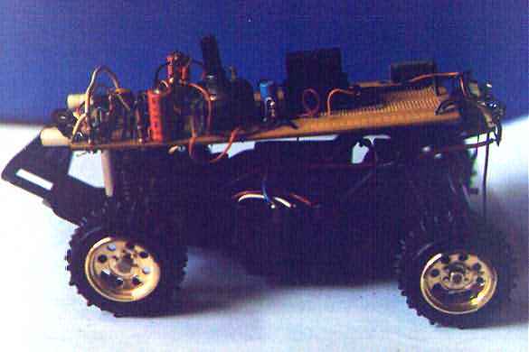 |
The frontal sensors must have a clear view of what lies ahead...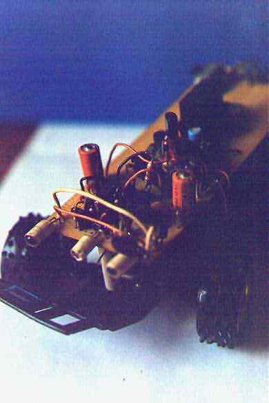 |
Proper sensor alignment must be done with a static object at a certain distance from sensors.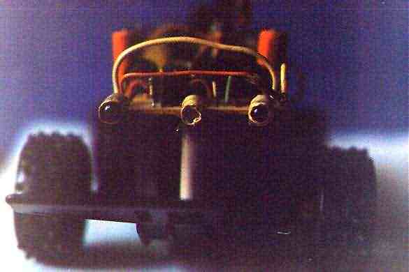 |
SOME TIPS ABOUT SENSOR ALINEMENT AND CALIBRATION
IR emitters leds irradiate a cone of infra red light therefore some experimenting is necessary to determine position and best shrouding in order to prevent that the FT receptor located in the middle receives direct IR emissions.
In Fig 2 are shown the main beams of the IR emitters (in red) and the lateral beams (in orange). The FT phototransistor has a reception cone depicted in sky-blue. Note that direct lateral emissions of infra red light reach the FT. We don't want this direct type of illumination, what we want are the reflections of the main IR beams (in red) produced by an object ahead.
Fig 3 depicts how we may prevent lateral emission beams from reaching the FT. If we put some kind of sleeve or shroud around the emitter leds we may control how much this lateral beam will expand, i.e.: the angle of aperture.
Remember the four photographs of the car shown above? If you click on the "front view" photograph you'll see a close-up of the shrouded emitters. Certainly you may also shroud the FT.
All we have discussed relates to the horizontal plane, but similar considerations can be made considering the vertical plane. Precautions against ground reflection should be consider, i.e.: the angle from horizontal plane the IRs aim for.
It's not very difficult to calibrate the PLL reception module, just follow the instructions:
According to Fig 4a the circuit is energized but the motor is turned off. Put an obstacle at about 4 inches ahead of IR emitters and slowly turn the PLL pot until the capture led turns on. Now the PLL is tuned; mark the pot value at which the capture was achieved.
As there may be harmonics of the main capture frequency, continue marking different positions at which the capture led turns on. Later, when we move farther away the obstacle, this points will disappear.
Now according to Fig 4b we repeat the process of Fig 4a but with the obstacle at position #2. Repeat the process at farther distances: i.e.: position #3.
You'll see that at greater distances from the sensors, the other marks in PLL pot disappear, just leaving only the main frequency f0.
ABOUT THE CIRCUIT
Here's there's no big deal. See the main circuit in a new window click here,
while you continue reading this description (you may call the new window every time it's needed).
Let's start from the left: a NE 555 is configured as a astable oscillator running at 18 KHz. Its output (pin 3) goes into a transistor which drives the two IR leds. You may notice a 100 ohm trimmer to adjust IR intensity. This is useful if you want your batteries to run longer or if there's a lot of bouncing reflections from around that confuses the FT. A 220 uF electrolytic cap and a 1N4001 diode serve as decoupler to isolate the transmitting module, thus preventing the 18 KHz signal to propagate by the main +6 volt bus. You may select another value or even insert in parallel a 100 nF ceramic disc cap.
Here you have the phototransistor FT and an amplifier stage with some selectivity around 18 KHz, the received signal continues and enters the NE567 PLL (Phase Locked Loop). This integrated circuit works as follows: when the arriving signal has a frequency equal to the one programmed into the 567, pin 8 goes to ground. The central capture frequency f0 is programmed by the RC line (30 Kohm pot, 43 K resistor and 1 nF ceramic cap) between pins 5,6 and ground. Capacitors between pins 1 and 2 set the width of the frequency capture window, which means that the 567 will "capture" any frequency between f1 and f2.
The reception of a signal with different frequency than the 18 KHz selected in the PLL, keeps pin 8 at high (+6v). Upon reception and capture of a 18 kHz signal, pin 8 goes to ground thus turning the capture led on. The junction between the two 1 kohm resistors, initially at +6 volts now goes to approximately +4 volts (remember the 1.6 to 2 volt drop in the led when conducting). Now, with +4 volt at the base, the PNP transistor will be turned on (we need the base at least 0.7 volt below the +6 v line), enabling us to use this PNP transistor as a switch.
With the PNP transistor turned on, we have now an instant charge on the 10 uF electrolytic capacitor connected to the PNP collector. But this charge is applied to a 100 kohm resistor, thus generating a timing constant equal to 2xRxC. In our case about 2 seconds: This means the collector of the PNP will decay to ground in about 2 seconds. The next NPN transistor has its base connected to the PNP collector, so, when the PNP's collector suddenly displays +V, the NPN is turned on and will be on for the time selected in the RC constant.
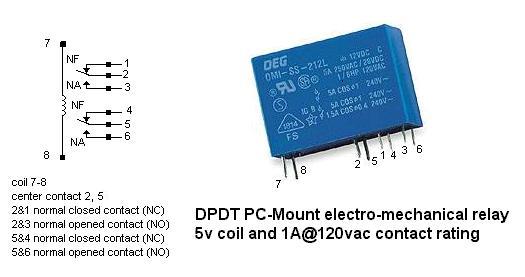
This NPN drives a relay with 2 normal-close contacts. This relay will be energized for the time the RC and the NPN transistor timing circuit is programmed.
In this module the motor's supply is taken from +6 and +3 volt points. The relay contacts are connected in such a way as to invert the motor supply polarity, thus enabling motor reversion upon signal capture.
The relay is a PC-Mounted electromechanical relay, with a coil of 5 or 6vdc and contacts with a rating of less than 1 Amper (the motor draws less than 1 amper for sure). Is DPDT type (double pole, double throw). Radio Shack has many type of these, catalog number #900-2334, OEG brand, model OMI-SS-2-05D, about $2.50 each. See the following picture for details: