BOUNCING LIGHT
9 OUTPUT UP-DOWN COUNTER
by Le Magicien
Do you remember the movie "The Day the Earth Stood Still"?
Remember the impressive cyclops robot that had a scanning eye that swept back and forth? Cool, right?
What about Kitt the "Knight Rider"?
Well, with that in mind (and some emails from friends all over the world starting by England -that's you Jon, thanks for asking!-) I tinkered around and came with this design that works pretty well -... on the protoboard ...;-) The idea is to have something moving back and forth like the led shown below:

In our case, you have 9 outputs you may use (
Q0 to Q8) to actuate any load you want, from leds or lamps to motors!

CIRCUIT THEORY & DESCRIPTION
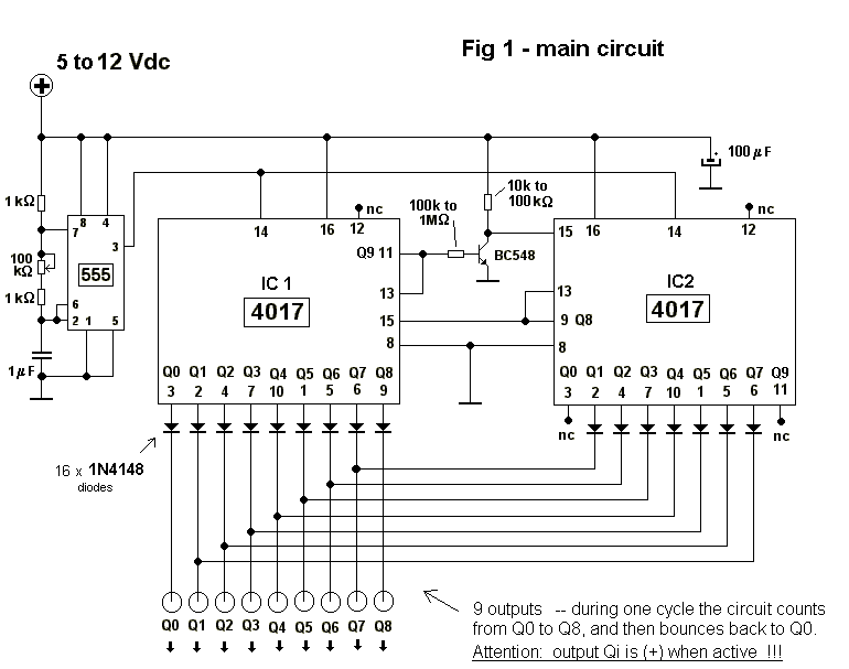
Two 4017 cmos decade counters are wired together so as to count from 1 to 17, but in this case the second part of the counting, done by the second 4017 -IC2-, is used to count down (via a diode matrix).
The clock pulses are given by a 555 universal time wired as an astable oscillator, very low frequency (between 1 and 20 Hz aprox), but if you like you may use any other clock instead of the one built around the 555 timer.
Let's analize the circuit.
Pulses are applied to pin 14 of IC1 and IC2 -clock inputs- of 4017 decade counters. With each pulse, output pins 3, 2, 4, 7, 10, 1, 5, 6, 9, 11 (in that order) go high for the duration of the pulse.
Considering IC1, last pulse makes pin 11 momentarily high; this (+) signal goes to pin 13 IC1(-clock enable-) which, being held high , commands the counter IC1 to ignore pulses (thus IC1 stops counting).
Same (+) signal acting on transistor BC548 now grounds pin 15 of IC2 (which was being held positive). This pin is the counter Reset, when pulsed momentarily high makes the counter to start counting from zero, that is, counter will start from output Q0 (pin3).
Now IC2 counter starts counting. When output reaches Q8 (pin9) it pulses high pin 13 and the counter stops counting (as we did in turn with IC1). Now pin 15 of IC1 is reseted and IC1 resumes counting while IC2 is not enabled.
While IC1 is counting outputs from IC2 are disabled, when IC2 is enabled IC1 is disabled. Output signals coming out from IC2 now are sent in inverse order to IC1 outputs so as to now start counting down. Diodes at each counter output prevent interference between them.
Now we have an output that bounces back and forth from Q0 to Q8. This outputs are high that is (+) when active.
Main circuit is given in the schematic above. (Please note that in IC1 pin 13 is connected to pin 11, while in IC2 pin 13 is connected to pin 9 ; also note that in order to prevent erratic behavior, a decoupling capacitor is used 100 uF at the positive supply!!!).
DRIVING BIG LOADS
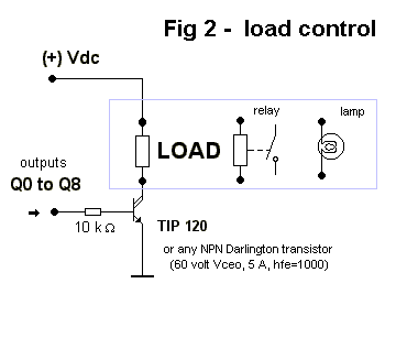
HEAVY LOADS may be actuated using the driver depicted below. You must choose the transistor in order to properly actuate upon the load, but a good choice will be a TIP 120 npn darlington transistor, capable of 5 amperes! Transistor's base is connected to Q0-Q8 outputs via base resistors (between 1 to 10 kohm aprox). -See picture below:


