HENRIQUE LAVIGNE : E-MAIL : [email protected]
TEL : 55-24-2647-4766
VEHICLES
WITHOUT FUELS USE.
This
patent has several technological
innovations of which we highlighted:
I
– PROPULSION.
The
innovation concept that characterizes “invention” and make an Invention
Patent is a system to be projected for common vehicles, automobiles,
trucks, bus or motorcycles, with their our original motors, only are adapted
to move in these electric highways sparing fuels use.
II
- MAGNETIC SUSPENSION AID.
The
invention creates an adaptation in common vehicles to receive from highway a
“magnetic repulsion” that is a new levitation concept.
That
relieves the vehicle weight on their suspensions, axes, tires and wheels.
III
- LEVITATION.
The
patent also creates a system of magnetic levitation for application in special
self-driven vehicles that are moved LEVITATING on magnetic fields.
I
- VEHICLES ELECTROMAGNETIC PROPULSION.
They
uses the almost secular physical law of the lineal asynchronous motors, that
comes to be the same used, tested and approved, in trains Maglev, Japanese,
Germans and French.
Invention
propulsion system there is not limitative only a road or a track,
electromagnets are applied in every tracks width that form the highways,
allowing the concomitant displacement of several vehicles to different speeds.
The
vehicles have accelerator allowing like this pass.
Illustration
1 is a top view
of an electric highway constituted of three tracks, A, B and C.
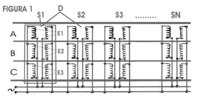
Transversely
are put in the highways, below this level, several electromagnets, are covered
and they don't appear. The reels E1, E2 and E3 represent them.
This
disposition is merely explanatory, they can be constituted of several
electromagnets distributed in every width of one or more tracks and currents
three-phase can feed them.
These
electromagnets form the series S1, S2, S3....Sn, that are put at certain
distances D for every extension of the highway.
The
electromagnets of each series are linked in parallel and they have the same
polarization.
Each
series electromagnetic reels are linked with alternate polarizations, one
after other, as shown in the outline.
Is
the classic outline of a lineal asynchronous motor of two-phase current. In a
roof fan, the electromagnets are willing in ring.
When
the alternating current is applied, each series of electromagnets is with a
polarization contrary to polarization of contiguous series, as current is
alternated these polarizations alter and they spread as a wave.
In
the fans, this field magnetic drags a polar piece that is linked to helix
making her to rotate.
In
the electric highways, a polar piece, that is a reel in short circuit or a
permanent magnet, is adapted in the part of bass of vehicles and, to being
dragged by magnetic field, drags with itself the vehicles.
This piece besides moving the vehicles serves as accelerator.
Each highway can be programmed for a determined final speed, in
function of the distances among the electromagnets series, the applied current
frequency and the system income.
They
are represented in Illustration 2, an automobile that moves in the
track A, for low speed, a truck that moves in the track B, for
average speed and a motorcycle in the track high-speed C.
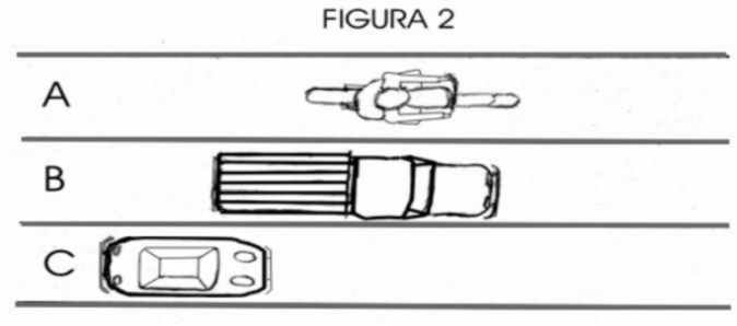
As
the three tracks use electromagnets in parallel and the same current feeds
them, is possible to reach programmed maximum speed in all tracks. Other
systems can use magneto serials for each track, with different frequencies,
obtaining final speeds for each track.
Own
accelerator controls each vehicle speed, that is, the highway allows
displacements until the maximum speed programmed, and the driver is that
controls the speed of vehicle.
Basically
the accelerator of the vehicle is a mechanism that alters the distance of this
magneto with the soil.
The illustration 3 represents a transversal schematic cut of a vehicle on a highway. Shows an explanatory system using a simple lever, in the practice, elaborated mechanical systems, electric systems and hydraulics systems will be used.
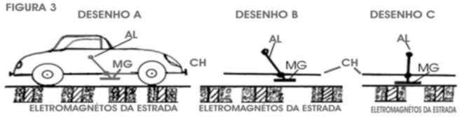
In
the vehicle chassis CH is applied a lever AL that is shown in
three positions in the drawings A, B and C.
The
lever AL controls the MG magnet permanent distance in relation
to the soil.
In
A, lever Al
is pulled back, what suspends the magneto MG of soil; leave out the
magneto of highway magnetic field, whose polarities move around. The
automobile, in this case is stopped, or walking with your own motor, because
your traction magneto is far enough of magnetic field.
In
B,
lever AL is pushed slightly forward, doing with that magneto approaches
of the magnetic field and begin to be dragged by him. The automobile begins to
move even with your turned off motor.
As
in a conventional accelerator, the driver determines the speed of your
vehicle, approximating or moving away the soil’s magneto.
In
C is shown the
case of total acceleration and speed, lever AL is all-forward, the
magneto is more possible closest of magnetic field and maxim influence
suffering, therefore, maxim speed.
The vehicles move until electric highways with their own motors. When enter in the electric highway, enters in performance the magneto adapted in vehicle inferior part, the engine can be off.
The
propulsion system can be used initially as engine aid, only in ascents of
mountains with long acclivity kilometers.
Heavier
vehicles would use their own engines and electromagnetic propulsion, saving
more fuel in few kilometers than lighter vehicles in many kilometers, would
aid them.
The
system also allows total engines elimination, in special vehicles that only
move in electric highways.
II
- SUSPENSION MAGNETIC AID FOR VEHICLES.
The
Illustration 4 displays a highway longitudinal lateral cut.
Shows
magnets powerful series with their polarities guided in a same sense applied
at certain distances one of the other.
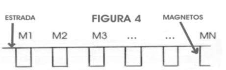
These
powerful magnets don't need to be necessarily superconductors, because that
spends a lot of energy; they can be the modern magnetos of rare lands.
The
Illustration 5 is a same HIGHWAY top view where series M1, M2,
M3......MN, is seen forming a road as a trail, where vehicles are moved.
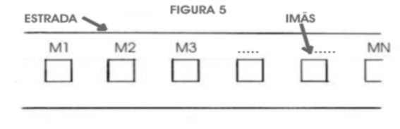
Below
of vehicles potent permanent magnets are put with same polarities guided for
the tracks magnets, so that there is repulsion among vehicles highways magnets
series.
This
repulsion creates a sustentation force for vehicle, reducing weight on the
suspensions, axes, rollerball, wheels and tires.
Is
very clear that system doesn't reduce vehicle weight on soil, system divides
vehicle weight, a weight part is sustained by magnetic field created by
magnets and other part of weight on the tires.
Descriptions
is merely demonstrative, just shown a magnets row, in practice they can be
applied many rows, so much in highways as below in vehicles.
The
magnets rows can be applied in only a highway track, or applied every width of
highways, in their several tracks allowing vehicles pass another.
Logically
vehicle stops receiving magnetic flotation when leaves magnetos to move for
another track.
III
- MAGNETIC LEVITATION FOR VEHICLES IN HIGHWAYS.
Invention
creates a system were vehicles are move in special highways that create a
magnetic field to levitate these vehicles.
The levitation system uses the same Maglev trains concept, "magnets with same polarizations are repelled and making to levitate the vehicles ".
The
subject is old and well documented.
The innovation concept that characterizes "invention" and turns a Patent is to be the system projected for common vehicles, automobiles, trucks, bus, etc.
Creates a magnetic corridor for vehicles were they move, that is, only a track and, logically, it doesn't allow pass.
Combine
two systems, magnetic propulsion and magnetic levitation, vehicles can
levitate, that is, they be moved on a magnetic field.
Also
creates a new concept to maintain vehicles centered on track.
We
will describe only the levitation system with Illustration 6 aid that
represents a transversal cut of track P1 and vehicle V1.
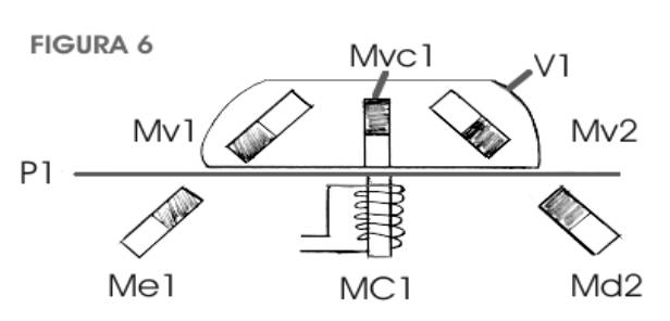
In
highway P1 are mounted, below your level, two permanent magnets rows
forming two series. They are put at certain distances in every highway
extension, they are hidden and they are not visible,
In
transversal illustration cut they are just shown one magnet of each series, Me1
of left series and Md2 of right series.
In
highway P1 are mounted below your level two permanent magnets rows
forming two series. They are put at certain distances in every extension of
the highway, they are hidden and they are not visible,
Their
polarizations are north upward, show in the illustration as dark part magnet
drawing.
Above
track P1 is the vehicle V1 with two series of permanent magnets
put below, shown in the transversal cut only magnets Mve1 and Mvd2
of each series, with their polarizations north down.
The
two vehicle magnets series are repelled with two magnets series put in track P1
creating sustentation for the vehicle V1.
Magnets
inclinations help to center the vehicle on the track.
Definitive
solution is reached with a electromagnets series Mv1 put in center of
vehicle, shown in the transversal cut, with south polarization down, this make
an attraction for the track’s magnets Me1 and Md2.
In
track center, is an electromagnets series MC1, shown in transversal
cut.
This
electromagnets series extends for every track extension.
All
electromagnets have your polarizations south guided upward, and they attract
vehicle permanent magnets series Mvc1, with variable intensity,
electronically commanded, obtaining administration on magnetic fields
that they make to levitate the vehicles, maintaining them centered in track.
The
system is not a static process, when stopped Mvc1 is taken the maxim
potency and force the vehicle to touched soil firmly.
This summary is an explanation of general operation of the systems, other complementally technologies will be implemented in the specific projects for each use purpose.
Like
this the vehicles levitation system can be complemented with other resources
to avoid skidding in curves, being the most obvious system the elimination of
curves. They can be aided in curves by mechanical processes, as fences, rails,
supplemental electromagnetic energies, etc.
The brakes system is commanded by electromagnets central series (Mc1) of the tracks.
HENRIQUE LAVIGNE : E-MAIL : [email protected]
TEL : 55-24-2647-4766