| Chassis
Fabrication December 1st - 22nd |
|
|
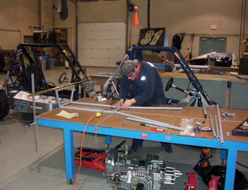
Here are some pictures of the
countless hours we spent in the shop day after day to fabricate our
chassis. Please note this does not include engine mounts, tabs, seat/fire
wall, or anything else not pertaining directly to the chassis.
Laying out PVC model for mock up

Tube was bent using a heat gun (large hair dryer) and screws drilled into
cardboard & wood. It is important to heat on the outside of the bend or
the tube will kink. Notice a pail of water to the right. This was used to
quickly quench the hot partially melted plastic to room temperature so
that it hold its position.
Laying out PVC with an old piece of brass pipe and string. Believe it or
not our PVC mock up tolerance was less than a few mm's. Hot glue was used
to attach members.
James sitting in the PVC mockup with petal assembly mock up in place.
This is a picture of a jig we made to hold the seat at the new angle of 30
degrees.
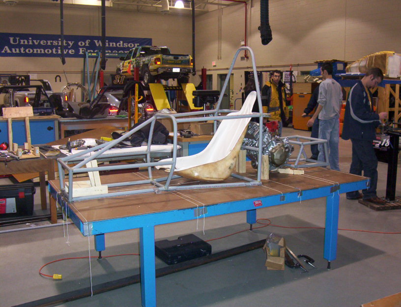
Most of PVC mock up completed with buck engine mounted in to give us an
idea of clearance.
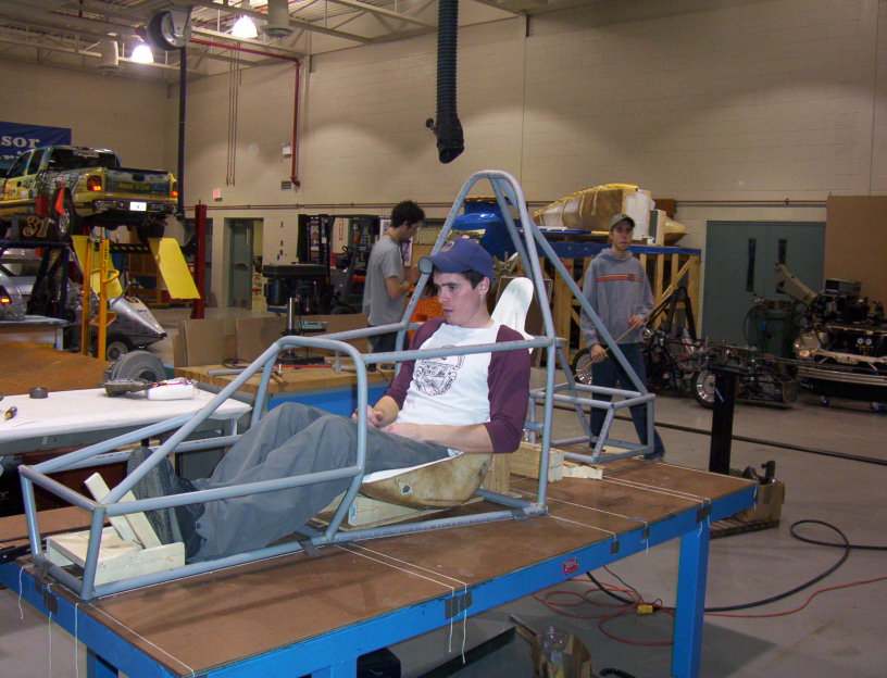
Pat sitting in the completed PVC mock up.
 |
Again strings were used for chassis layout lines. Cardboard
was an asset for designing front bulk head, rear box, main roll hoop and front
roll hoop. Precise angles could be laid out and checked on diagram after slowly
being bent. Almost all jigs for chassis were designed using 2 X 2 X 1/8 angle
iron.
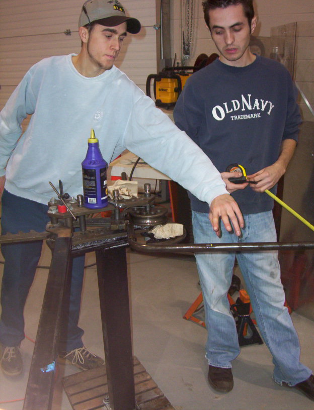
Tube bending was done using the tube bender in the CARE
building. Notice the use of oil on the mandrel to allow smooth bending. It is
important to note that the school has only three mandrels: 3", 5.5" and 10".
Also we found the 3" mandrel caused kinking on tube with thinner wall sections.
Tube bending must be done in one shot because it was difficult to get the bent
tube back into the tube bender in the exact plane and location were it was
previously.
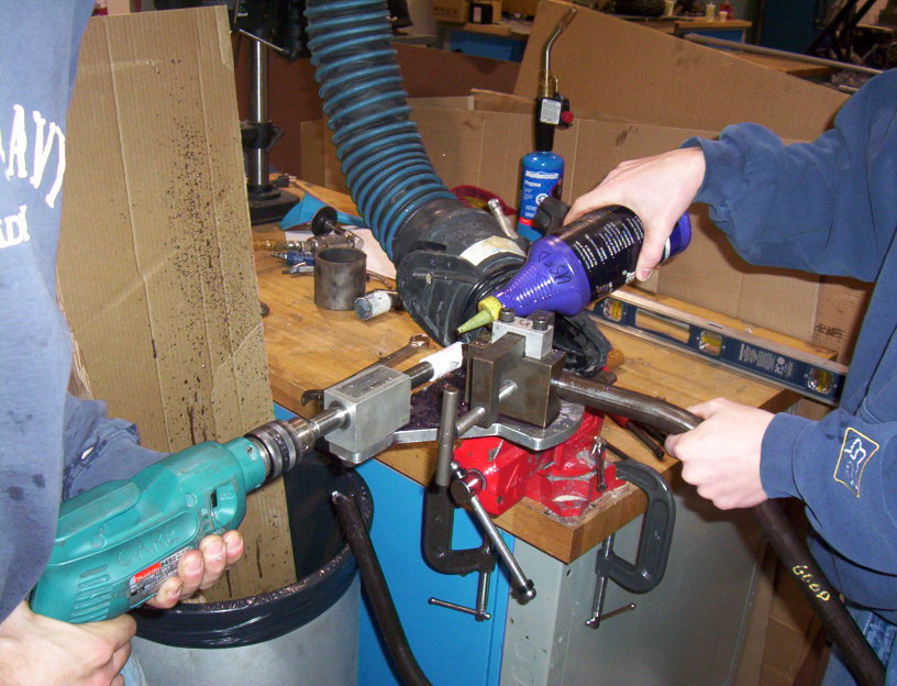
Tubes were precisely notched using a tube notcher. Angles from
0 - 45 degrees could be used.
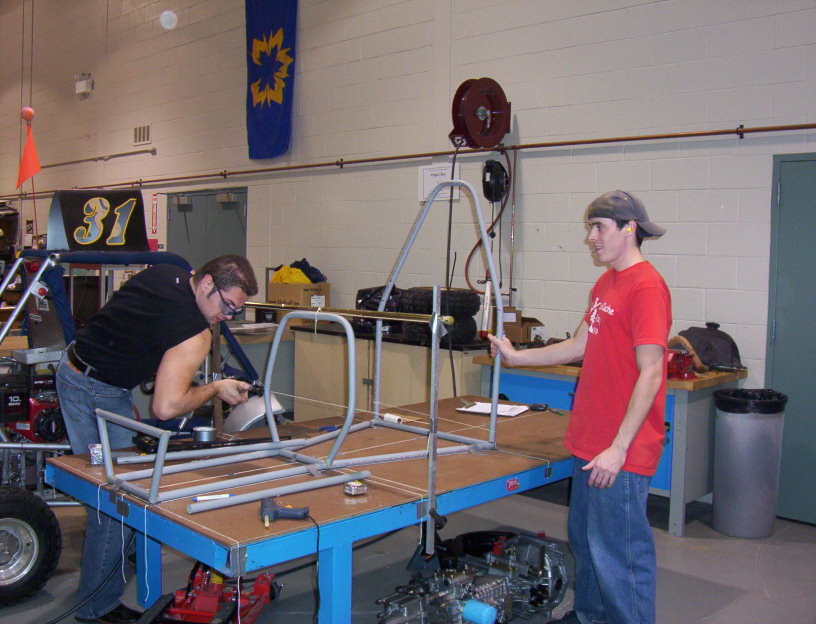
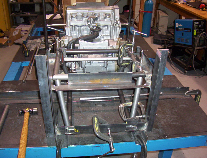
Clamps were greatly underestimated. We purchased over $500
worth of clamps for the jigging application. Notice the use of angle iron and
clamps. Most of the angle iron was cut, laid out and clamped and then MIG
welded., but MIG welding was not a done to temporary jigs or to the table.
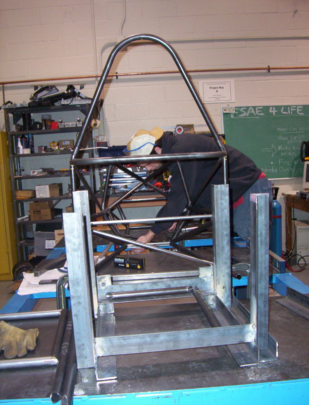
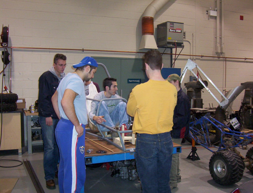
Rear box jig. You will notice later how small the jig becomes.
Rear box jig ready to be welded. Tubes were aligned by having
two 45 degree angles cut into them. The most time consuming part of the entire
chassis was completing the four vertical rear box members because of the tedious
grinding involved. Proper fit up is essential because during welding a lot
more heat will be put into the weld to fill in the gaps, causing distortion and
residual stress.
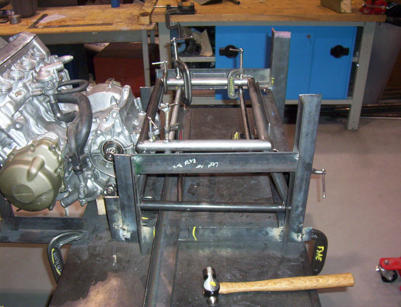
Another photograph of the rear box.
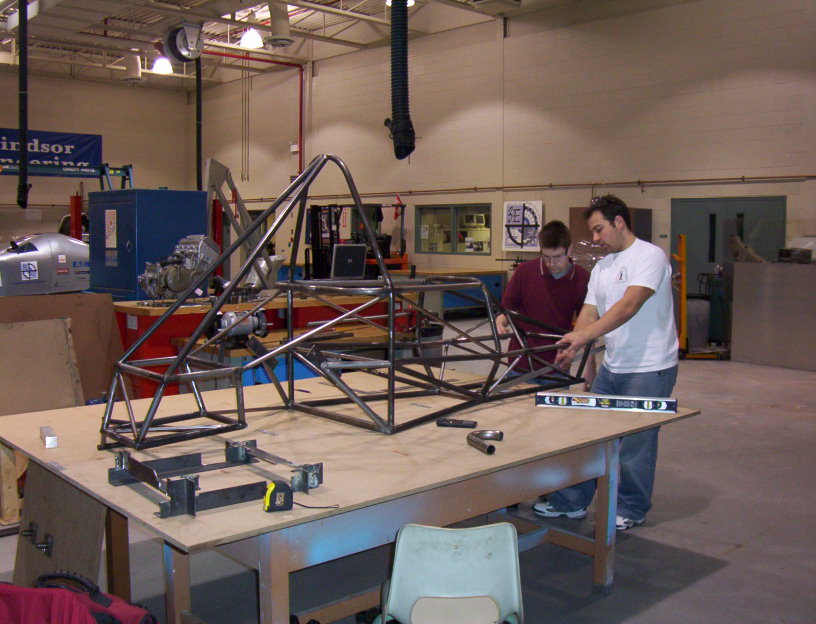
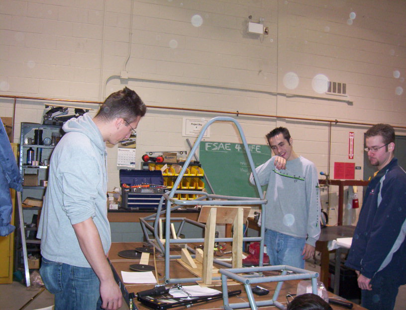
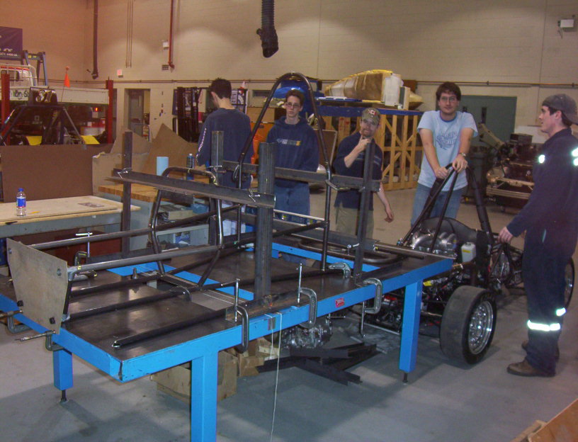
Completed chassis. Notice the new table for suspension layout.