Designing an Adapter Plate
 Well, since Timm Cooper and the BCB guys were no longer in the business of making adapter plates
for Ford engines, I was on my own. I did a lot of research, and must have sent a dozen odd
e-mails to Advance Adapters, Novak Conversions, and some of the better known manufacturers of
these sorts of things. None of them made this adapter, and none of them were interested in
taking a whack. I even called Timm Cooper back and offered to buy his plans from him, but he
was not willing to part with them. So, I was on my own!
Well, since Timm Cooper and the BCB guys were no longer in the business of making adapter plates
for Ford engines, I was on my own. I did a lot of research, and must have sent a dozen odd
e-mails to Advance Adapters, Novak Conversions, and some of the better known manufacturers of
these sorts of things. None of them made this adapter, and none of them were interested in
taking a whack. I even called Timm Cooper back and offered to buy his plans from him, but he
was not willing to part with them. So, I was on my own!
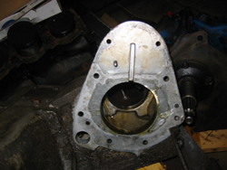
 Phase one was to get a good feel for the problem, and take some preliminary measurements. I
must have spent a solid weekend in the garage with a pair of calipers, graph paper, and a host
of other measuring techniques, getting a grip on the dimensions of the two faces that were going
to have to mate. I started making rough engineering drawings on graph paper, and began
visualizing the piece.
Phase one was to get a good feel for the problem, and take some preliminary measurements. I
must have spent a solid weekend in the garage with a pair of calipers, graph paper, and a host
of other measuring techniques, getting a grip on the dimensions of the two faces that were going
to have to mate. I started making rough engineering drawings on graph paper, and began
visualizing the piece.

 When the first draft was done, I decided that a rough wooden model would be the way to go, and
help me tackle some of the more difficult aspects. I took a 5/8" piece of plywood, some of my
sketches, and got crazy in the garage. When the sawdust was settled, I had a reasonable mock-up
of the part that I was going to have to make.
When the first draft was done, I decided that a rough wooden model would be the way to go, and
help me tackle some of the more difficult aspects. I took a 5/8" piece of plywood, some of my
sketches, and got crazy in the garage. When the sawdust was settled, I had a reasonable mock-up
of the part that I was going to have to make.
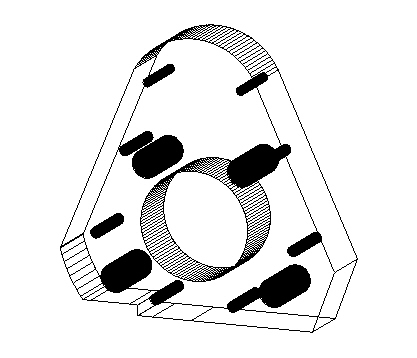 I initially was going to try and draft the technical drawings by hand, but decided to try a more
modern path. I downloaded a 30-day trial version of the commercial design software called
DesignCAD 3D Max, and got silly. It really is a useful tool, and I highly recommend it for
anyone who needs to purchase some design software. When I was done with the primary view, I was
even able to generate a 3D view of the part. To get the measurements down, I began printing
full scale copies of the adapter, then meticulously cutting all the holes out. I would match
these paper cut-outs against the actual faces, and make adjustments. After 2 weeks, I had a
very suitable set of diagrams.
I initially was going to try and draft the technical drawings by hand, but decided to try a more
modern path. I downloaded a 30-day trial version of the commercial design software called
DesignCAD 3D Max, and got silly. It really is a useful tool, and I highly recommend it for
anyone who needs to purchase some design software. When I was done with the primary view, I was
even able to generate a 3D view of the part. To get the measurements down, I began printing
full scale copies of the adapter, then meticulously cutting all the holes out. I would match
these paper cut-outs against the actual faces, and make adjustments. After 2 weeks, I had a
very suitable set of diagrams.
I also have to mention that during this period, I was also doing all the design work on the new
T-18 output shaft that I was going to have to fabricate. I measured the existing Ford output
shaft, and took dimensions from the IIA output shaft that was going to have to go on. I also
decided that rather than tear apart my perfectly good IIA transmission, I bought a donor
mainshaft from Bill at TLR for a very reasonable price.
 When I was done, I shopped around my CAD design to several local machine shops, and several were
willing to take on the work, but for close to $900-$1000 each. I was toying with the idea of
enrolling in a community college course just so I could access their CNC machines, when I found
a guy at work who is a master machinist, and does work on the side. I was skeptical until I
discovered that he had a full-blown computer-controlled CNC machine IN HIS GARAGE! I bought a
piece of 6061 off of eBay for $30, and he made the adapter off my diagrams for a teeny
fraction of the price! It fits perfectly!
When I was done, I shopped around my CAD design to several local machine shops, and several were
willing to take on the work, but for close to $900-$1000 each. I was toying with the idea of
enrolling in a community college course just so I could access their CNC machines, when I found
a guy at work who is a master machinist, and does work on the side. I was skeptical until I
discovered that he had a full-blown computer-controlled CNC machine IN HIS GARAGE! I bought a
piece of 6061 off of eBay for $30, and he made the adapter off my diagrams for a teeny
fraction of the price! It fits perfectly!
So, if anyone else is interested in this conversion, drop me a line...
More Chassis Preparations
created and maintained by
Matt Atkins
Back to the Main Page