Click on the pictures to see them.
-total lenght = 21.65 inches
-wound lenght = 20.98 inches
-diameter = 4.32 inches D/L ratio = 1/4.8
-number of turns = 2665 with # 32 enamel wire
-calculated inductance = 144547.81 uH
-self capacitance =8.3143 pF
-self resonance at 145.25 kHz
-little toroid: calculated capacitance = 11.77 pF
-medium toroid: calculated capacitance = 16.30 pF
-total lenght = 9.84 inches
-wound lenght = 3.93 inches
-diameter = 7.08 inches
-number of turns = 10 with 3 mm solid copper wire
-taped at 8 turns
-calculated inductance = 17.61 uH
-MMC style made with 2200 nF @ 630 V caps
-3 strings in parallel
-one string made with 22 caps in serie
-final value = 300 nF @ 13860 V
Fres with the little toroid (now in use) = 101.15 kHz
Fres with the medium toroid = 96.5 kHz
-classical self resonant driver (antenna, 1N4148 clamping diodes, 74HC14 hex inverter (5 V), UCCs inverter and non-inverter chips (12 V), 1N5819 on the UCCs outputs, 1 uf coupling cap to the GDT. To prevent the discharges to electronics the driver is located under the resonantor.
The half bridge is made with two BUP 307 (1200 V @ 35 A) protected with MUR3060 ultrafast diodes and 30 V @ 1 watt Zenners on the gates. Gate dumping resistors = 5.6 ohms. 2.2 uF @ 630 V caps on the cap divider. Each IGBT with its own heatsink.
I used toroidal ferites harvested from monitor cables or cores from sources which are covered with some kind of enamel (are the best). The transformer has 5 windings with 13 turns, twisted together. One is the primary, the others are put in serie (each two) to make a 1:2:2 GDT (24 V on IGBT gate).
Built around a 555 chip with variable ON and OFF times.
Turning to 0 the 500 kohms pot, I can use the interrupter
for the mini- ISSTC setup.
-220 V / 250 V @ 10 a variac with a 16 A fuse
-full wave rectifyed with a 1000 V @ 35 A bridge on a heatsink
-DC bus capacitor: 470 uF @ 400 V (until now).
100 nF @ 1600 V in serie for a total value of 298 nF @ 4800 V
little toroid used
interrupter: C = 1 uF, ON time = 1-10 msec, PRF = 2-50 pps (just keeping the PRF low to protect the IGBTs).
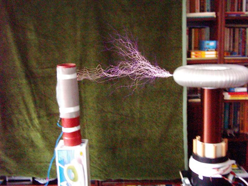
RESULTS: 16 inches streamers
interrupter: C = 1 uF, ON time = 1-10 msec, PRF = 2-50 pps
RESULTS: 20 inches arcs
I made a few experiments using different ON times and pulse frequencies. I used the same toroid (the little one), the same voltage input, same DC bus cap, the same gap between the toroid and the grounded wire. The results are here:
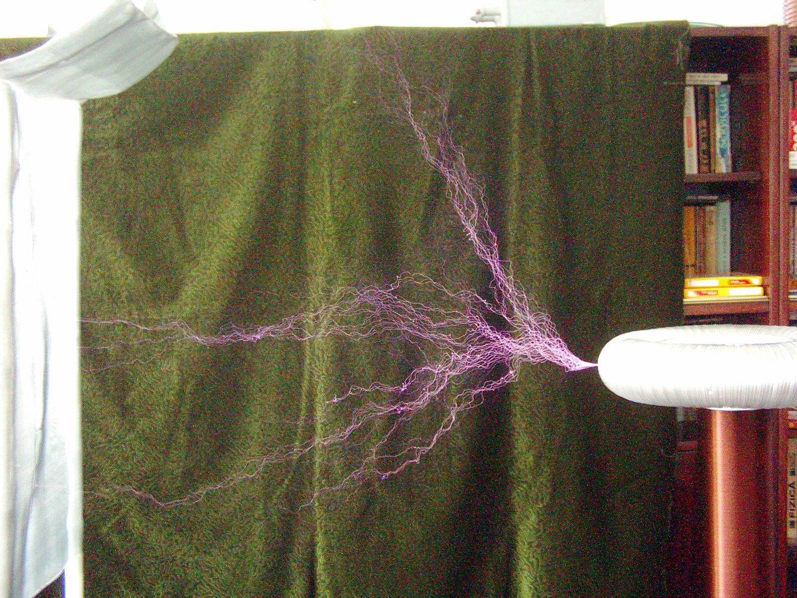
The streamers don't grow after some ON duration, but become very intense and bright
The streamers grow and give arcs to ground, but the intensity of the discharges is somehow lower.
It seems that I will not have 40N60s, so I will make a full bridge with BUP314 IGBTs (1200 V @ 52 A). I need a new driver with two pairs of gate driver chips, 15 V input (30 V output from a 1:2:2:2:2 GDT transformer). Maibe I will use a CT feedback.
Because I have ferrites of different sizes and materials I choosed the design with a single gdt for a H-bridge. Two paralleled primaries and 8 secondaries, seried each two, for a 1:2:2:2:2 gdt
It is the same driver as for the half bridge, but with two pairs of gate drive chips, 15 V input on UCCs (LM 7815 voltage regulator) and more protection on UCCs (0.1 uF ceramics, 20 uF tantal and 470 uF litics.
Little ferrite toroid with 2 turns primary and 100 turns secondary. 10 kohms resistor on the output. I will use this if the sparks will be too long :)
16 caps (5 uF @ 600 V) in serie for a total of 312 uF @ 9.6 kV
Many thanx to Mazzilli Vladimiro for these caps.
Made with 4 BUP314 IGBTs (many thanx to Vladimiro Mazzilli), with MUR3060s paralleled diodes, 5 uF @ 600 V caps on the rails, 5.6R resistors on gates and 33 V @ 1.3 W zenners. The IGBTs are mounted on three heatsinks held together by a plastic matrix.
I replaced C with a 200 nF cap and the pot for R(OFF) is 1 Mohms now.
T(ON) = 200 microsec- 2 msec (still too high)
F = 5- 500 pps
It would need a 2.5 Mohms pot for R(OFF) to have a larger range for the F (pps), even at lower ON times.
My new driver has some bugs. The signal from the interrupter doesn't go to the UCCs, so it works in CW mode. I have to debug it, a bad PCB design is the problem, I think. Until then, I will use my old driver (from the half-bridge), with 2 pairs of UCCs stacked together.
It works!......but at 80 vac input I have severe flashing between primary and secondary. So my cilindrical primary is useless. I will use a flated primary made with multifilar cable (with insulated stranded wire conductors 3 x 2.5 mm). As result, even with lower coupling, the sparks are long, but I have to increase the input voltage.
New primary: 6 turns, wrapped together in a coil shape (8.26 inches diameter and 1.18 height). The multifilar conductors are twisted together at the ends of the coil. Calculated inductance Lc = 12.53 microH. It is a 5 minute made primary but performs as a charm.
with all the parts connected together. I had to add one more cap to my Cp (294 nF @ 10.2 kV for now).
Increasing / varying both the ON time and pps result in bright streamers, but only a few arcs to the target (set at 36 inches). It seems that it is best to keep the ON time at minimum (200 microsec).
I am not sure if it is perfectly in tune, I have to tincker a bit. Lower ON times and 300-400 pps, with even more voltage input would give longer discharges.
