
Basic
structure of a generic silicon PV cell
Single
crystal silicon isn't the only material used in PV cells. Polycrystalline
silicon is also used in an attempt to cut manufacturing costs, although
resulting cells aren't as efficient as single crystal silicon. Amorphous
silicon, which has no crystalline structure, is also used, again in an
attempt to reduce production costs. Other materials used include gallium
arsenide, copper indium diselenide and cadmium telluride. Since different
materials have different band gaps, they seem to be "tuned" to
different wavelengths, or photons of different energies. One way efficiency
has been improved is to use two or more layers of different materials with
different band gaps. The higher band gap material is on the surface,
absorbing high-energy photons while allowing lower-energy photons to be
absorbed by the lower band gap material beneath. This technique can result
in much higher efficiencies. Such cells, called multi-junction cells, can
have more than one electric field.
Batteries
What kind of batteries are used in PV systems? Although several different
kinds are commonly used, the one characteristic that they should all have in
common is that they are deep-cycle batteries. Unlike your car battery, which
is a shallow-cycle battery, deep-cycle batteries can discharge more of their
stored energy while still maintaining long life. Car batteries discharge a
large current for a very short time -- to start your car -- and are then
immediately recharged as you drive. PV batteries generally have to discharge
a smaller current for a longer period (such as all night), while being
charged during the day. The most commonly used deep-cycle batteries are
lead-acid batteries (both sealed and vented) and nickel-cadmium batteries.
Nickel-cadmium batteries are more expensive, but last longer and can be
discharged more completely without harm. Even deep-cycle lead-acid batteries
can't be discharged 100 percent without seriously shortening battery life,
and generally, PV systems are designed to discharge lead-acid batteries no
more than 40 percent or 50 percent. Also, the use of batteries requires the
installation of another component called a charge controller.
Batteries
last a lot longer if care is taken so that they aren't overcharged or
drained too much. That's what a charge controller does. Once the batteries
are fully charged, the charge controller doesn't let current from the PV
modules continue to flow into them. Similarly, once the batteries have been
drained to a certain predetermined level, controlled by measuring battery
voltage, many charge controllers will not allow more current to be drained
from the batteries until they have been recharged. The use of a charge
controller is essential for long battery life.
Wind Energy
The
wind-powered electricity generator would have the usual configuration of a
wind-mill designed to produce electricity.

The use of
different parts is as follows:
The wind
turns the blades, which spin a shaft, which connects to a generator and
makes electricity.
Utility-scale
turbines range in size from 50 to 750 kilowatts.
Anemometer:
Measures the wind speed and transmits wind speed data to the controller.
Blades:
Most turbines have either two or three blades. Wind blowing over the blades
causes the blades
to
"lift" and rotate.
Brake: A
disc brake which can be applied mechanically, electrically, or hydraulically
to stop the rotor in emergencies.
Controller:
The controller starts up the machine at wind speeds of about 8 to 16 miles
per hour (mph)
and shuts
off the machine at about 65 mph. Turbines cannot operate at wind speeds
above about 65 mph
because
their generators could overheat.
Gear box:
Gears connect the low-speed shaft to the high-speed shaft and increase the
rotational speeds
from about
30 to 60 rotations per minute (rpm) to about 1200 to 1500 rpm, the
rotational speed required by
most
generators to produce electricity. The gear box is a costly (and heavy) part
of the wind turbine and
engineers
are exploring "direct-drive" generators that operate at lower
rotational speeds and don't need gear boxes.
Generator:
Usually an off-the-shelf induction generator that produces 60-cycle AC
electricity.
High-speed
shaft: Drives the generator.
Low-speed
shaft: The rotor turns the low-speed shaft at about 30 to 60 rotations per
minute.
Nacelle:
The rotor attaches to the nacelle, which sits atop the tower and includes
the gear box, low-
and
high-speed shafts, generator, controller, and brake. A cover protects the
components inside the nacelle.
Some
nacelles are large enough for a technician to stand inside while working.
Pitch:
Blades are turned, or pitched, out of the wind to keep the rotor from
turning in winds that are too high
or too low
to produce electricity.
Rotor: The
blades and the hub together are called the rotor.
Tower:
Towers are made from tubular steel (shown here) or steel lattice. Because
wind speed increases
with
height, taller towers enable turbines to capture more energy and generate
more electricity.
Wind
direction: This is an "upwind" turbine, so-called because it
operates facing into the wind.
Other
turbines
are
designed to run "downwind", facing away from the wind.
Wind vane:
Measures wind direction and communicates with the yaw drive to orient the
turbine properly with
respect to
the wind.
Yaw drive:
Upwind turbines face into the wind; the yaw drive is used to keep the rotor
facing into the
wind as the
wind direction changes. Downwind turbines don't require a yaw drive, the
wind blows the rotor downwind.
Yaw motor:
Powers the yaw drive.
Shore based Wave
Power System
Where the
shoreline has suitable topography, cliff-mounted oscillating water column (OWC)
generators can be installed. OWC systems have a number of advantages over
the Clam and the Duck, not the least of which is the fact that generators
and all cabling are shore-based, making maintenance much cheaper.
The OWC
works on a simple principle. As an incoming wave causes the water level in
the unit's main chamber to rise (see diagram), air is forced up a funnel
which houses a Well's counter-rotating turbine. As the wave retreats, air is
sucked down into the main chamber again. The Well's turbine has been
developed to spin in the same direction, whichever way air is flowing, in
order to maximize efficiency. Although most previous OWC systems have had
vertical water columns, that in LIMPET is angled at 45° - which wave tank
test show to be more efficient.
OWC
machines have already been tested at a number of sites, including Japan and
Norway. A commercial-scale (500 kW) installation is due to be commissioned
on the Scottish Island of Islay in September 2000. The Islay OWC (known as
LIMPET) is a joint venture between Queens University, WAVEGEN, Instituto
Superior Técnico (Portugal), the European Union and Charles Brand
Engineering. It is the direct successor of an experimental 75 kW turbine
(built by researchers from the Queen's University of Belfast) which operated
on the island between 1991 and 1999. Another LIMPET is currently being
developed (at pilot-plant scale) on the Azores.
Construction
of OWCs
One of the
great problems with shoreline-based OWCs is their construction, which must
necessarily take place on rocky shores exposed to wind and waves. In the
case of the prototype Islay OWC system it was relatively easy to build a
temporary dam on the shoreline to protect the unit. However, LIMPET is a
much larger system, with a lip 20m wide. It was therefore ultimately decided
to build the unit back from the coastline and remove a bund to make the
system fully operational (see figure, below).
However,
both OWC-systems and ocean-wave systems suffer from trying to harness
violent forces. The first Norwegian OWC was ripped off a cliff-face during a
storm, the Islay station is completely submerged under storm conditions.
Thus, researchers are looking at other ways of generating electricity from
the ocean, and are increasingly turning to tidally-generated coastal
currents.
Power
from tidally-generated coastal currents
Over the
past forty years, there has been constant interest in harnessing tidal
power. Initially, this interest focused on estuaries, where large volumes of
water pass through narrow channels generating high current velocities.
Engineers felt that blocking estuaries with a barrage and forcing water
through turbines would be an effective way to generate electricity. This was
proved by construction of a tidal barrage at St. Malo in France in the mid
1960s. La Rance tidal power plant still provides 90% of Brittany's, and a
major refurbishment program (due for completion in 2007) means it will
continue in operation well into the new millennium.
Despite the
success of La Rance, no other major tidal barrages have been built since,
due in some part to environmental concerns. Barrages present a barrier to
navigation by boats and fish alike; reduced tidal range (difference between
high and low water levels) can destroy much of the inter-tidal habitat used
by wading birds; and sediment trapped behind the barrage could also reduce
the volume of the estuary over time. By the early 1990s, interest in
estuarine-derived tidal power had largely ceased, and scientists and
engineers began to look at the potential of tidally-generated coastal
currents instead.
As tides
ebb and flow, currents are often generated in coastal waters (quite often in
areas far-removed from bays and estuaries). In many places the shape of the
seabed forces water to flow through narrow channels, or around headlands
(much like the wind howls through narrow valleys and around hills). However,
sea water has a much higher density than air, meaning that currents of 5-8
knots generate as much energy as winds of much higher velocity. In addition,
unlike the wind rushing through a valley or over hilltops, tidally-generated
coastal currents are predictable. The tide comes in and out every twelve
hours, resulting in currents which reach peak velocity four times every day.
Two rival technologies -- tidal fences and tidal turbines -- are now being
developed to catch the energy of these currents.
Coastal
currents are strongest at the margins of the world's larger oceans. A review
of likely tidal power sites in the late 1980s estimated the energy resource
was in excess of 330,000 MW. South East Asia is one area where it is likely
such currents could be exploited for energy. In particular, the Chinese and
Japanese coasts, and the large number of straits between the islands of the
Philippines are suitable for development of power generation from coastal
currents.
Tidal
Fences
Tidal
fences (see figure 1) are effectively barrages which completely block a
channel. As discussed above, if deployed across the mouth of an estuary they
can be very environmentally destructive. However, in the 1990s their
deployment in channels between small islands or in straights between the
mainland and island has increasingly been considered as a viable option for
generation of large amounts of electricity.
The
advantage of a tidal fence is that all the electrical equipment (generators
and transformers) can be kept high above the water. Also, by decreasing the
cross-section of the channel, current velocity through the turbines is
significantly increased.
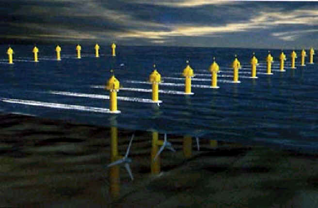
Tidal
Turbines
Tidal
turbines are the chief competition to the tidal fence. Looking like an
underwater wind turbine they offer a number of advantages over the tidal
fence. They are less disruptive to wildlife, allow small boats to continue
to use the area, and have much lower material requirements than the fence.
Tidal
turbines function well where coastal currents run at 2-2.5 m/s (slower
currents tend to be uneconomic while larger ones put a lot of stress on the
equipment). Such currents provide an energy density four times greater than
air, meaning that a 15m diameter turbine will generate as much energy as a
60m diameter windmill. In addition, tidal currents are both predictable and
reliable, a feature which gives them an advantage over both wind and solar
systems. The tidal turbine also offers significant environmental advantages
over wind and solar systems; the majority of the assembly is hidden below
the waterline, and all cabling is along the seabed.
There are
many sites around the world where tidal turbines could be effectively
installed. The ideal site is close to shore (within 1 km) in water depths of
about 20-30m. Peter Fraenkel, director of UK-based Marine Current Turbines,
believes the best sites could generate more than 10 megawatts of energy per
square kilometer. The European Union has already identified 106 sites which
would be suitable for the turbines, 42 of them around the UK. Further afield,
Fraenkel believes the Philippines, Indonesia, China and Japan could all
develop underwater turbine farms.
Solar Energy Cell
+
Tidal Energy Cell
+
Wind Energy Cell
=
<< Previous Page Next
Page>>