OPERATION
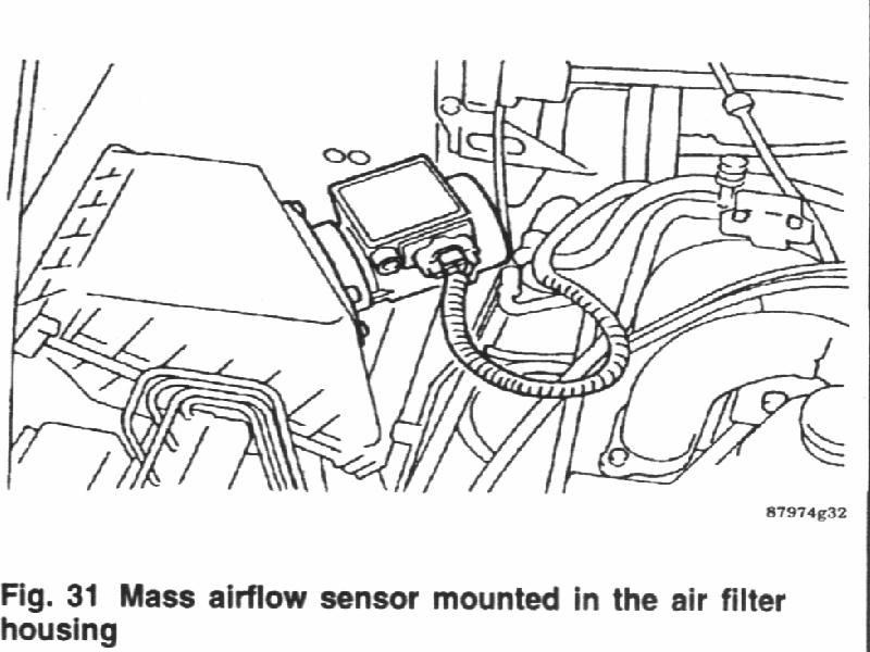
* See Figure 31
The EFI system incorporates a hot wire type MAF sensor with turbocharger (TC) equipped vehicles or a hot film type with non-TC vehicles. The meter converts the amount of air taken into the engine into an electrical signals by using the heat transfer between the incoming air and a heating resistor (hot wire) located in the air intake. Features of the MAF sensor include:
TESTING
Impreza
1. Turn the ignition ON.
2. Backprobe ECU connector terminal B5 with a high-impedance voltmeter. If the voltage is more than 0.3 volts check the wiring between terminal B5 and the MAF sensor. If the voltage is less than 0.3 volt, substitute a known good ECU and retest.
3. Backprobe ECU terminal C1 with a hagh-impedance voltmeter. The voltage should be 0 volts. If the voltage is more than 0 volts check for a short between C1 and a voltage carrying wire. If no short is presents substitute a known good ECU and retest.
4. Start the engine and backprobe terminal B5 on the ECU. The voltage should be between 0.8-1.2 volts. If the voltaue is not within 0.8-1.2 volts repair wiring between terminal B5 of the ECU and the MAF sensor. If voltage is within 0.8-1.2 volts continue testing to netxt step.
5. Backprobe terminal C1 on the ECU. The voltage should be 0 volts. If voltage is present inspect terminal C1 wiring to the MAF sensor for a short to voltage. If no short is presents substitute a known good ECU and retest.
6. Turn the ignition switch OFF and unplug the MAF sensor. Turn the ignition switch ON and check for system voltage at terminal 1 of the MAF connector. If voltage is not present repair wiring. If voltage is present, continue testing to next step.
7. Tum the ignition switch OFF and unplug the ECU connector. Check all wiring between the ECU and the MAF sensor for shorts, opens and ground. Repair as required.
8. If the wires check out OK, replace the MAF sensor.
Legacy
1. Unplug the MAF sensor connector.
2. Measure the resistance between the MAF sensor terminals and chassis ground.
3. Terminals 1, 2 and 4 should have 1 mega-ohm of resistance to ground.
4. Terminal 3 should have 0 ohms to ground.
5. Replace the MAF sensor if any of the resistance readings are out of range.
SVX
1. Switch the ignition ON.
2. Take the following voltage readings:
3. Start the engine and take the following readings:
4. If any of the MAF readings is out of range, check the harness and power supply. If the readings are still out of range, replace the MAF sensor.
REMOVAL & INSTALLATION
1. Disconnect the negative battery cable.
2. Disconnect the connector from the N1AF.
3. Remove the engine harness from the clip.
4. Loosen the hose clamps securing the air intake boot and remove the air intake boot assembly.
5. Loosen the MAF-to-air cleaner assembly bolts and remove the MAF.
TO INSTALL
6. Installs the MAF and tighten the bolts to 3-5 ft. Ibs. (47 Nm).
7. Install the air intake boot assembly and tighten the attaching clamps to secure.
8. Install the engine harness on the clip and connect the airflow meter connector.
9. Connect the negative battery cable.