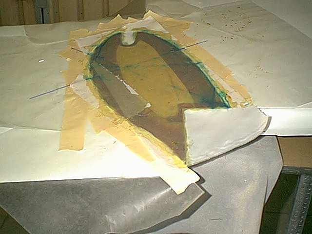
| Wing Repairs: Both the upper and lower skins showed cracks in the paint along a line running from about and inch aft of the main spar to the inner corner of the aileron cutout. Tapping with a coin indicated that there was debond in an area along this line and extending about 3" on each side. I sanded the paint and micro off this area and found indication that the skin had buckled. This was indicated by several white lines running in the same direction (outboard bolt to aileron cutout) but only a few inches long. It appears that when the winglet hit, it was loaded not only vertically but also in a drag direection or chordwise. The main spar is not very stiff in this direction, so the load is mostly carried in compression of the trailing edge. The area that debonded is the highest loaded area for this type load. The skins are only 2 plies of uni on the bottom and 3 on the top. I spoke to Nat and he indicated he had a similar failure after a similar landing. He said that he repaired it by injecting epoxy under the skins and holding them against the foam until cured. At that point I had not seen the white lines in the skins, so Nat did not know about that. Those lines indicate to me that the skin laminates are damaged and may not hold the loads they were designed for. I also feared that the foam underneath may be damaged and not carry the compressive load it should. I cut out the top skin over the debonded area. I found that the foam while mostly unscathed did have a small area about 1.5"x4" and about 3/4" deep that fractured. I filled the entire area with a thin layer of expanding foam and sanded it to flush with the existing skin. I then put 3 plies of uni over this area per the plans orientation and lapping onto the original skins afew inches. I also reinforced the corner where the strake and wing meet. I flipped the wing over and repeated this on the bottom. I also put 3 plies here even though the plans call for 2. There was no foam damage on the bottom so I only used micro over the existing foam. |