 |
 |
 |
 |
 |
 |
 |
 |
 |
 |
 |
 |
 |
 |
 |
 |
 |
 |
 |
 |
 |
 |
 |
|
|
 |
|
|
|
Why does my speaker sound harsh?
____________________________________
Or when is a BBC dip not a BBC dip? |
|
|
|
Chances are that you have either built or heard a speaker using a passive crossover that sounded excellent when played at low levels but as the volume rises the speaker becomes harsh, even to the point of being unlistenable. Typical measurements indicate the speaker is very flat through the mid and upper ranges and the response through the crossover is as smooth as a baby's butt. The immediate though that usually comes to mind is that there is some kind of resonance in a driver or the tweeter is being over driven due a too low crossover frequency or too shallow a roll off. While this may be the case, often the crossover per say is not the faults, well, sort of. The problem may lie in not considering an important factor in the design of the crossover: voice coil impedance variation with signal level..
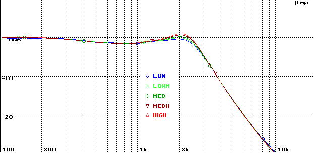
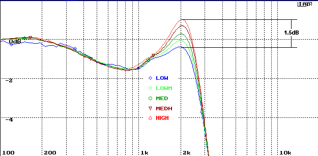
Below I have presented a series or response plots which clearly demonstrate what happens to a simple 2nd order electrical low pass filter when connected to a typical midrange driver. The driver used in the test is a Vifa MG14. The low pass filter consists of a 0.9mh series inductor with a 10 uf capacitor in shunt. The electrical response at the output of the filter was measured at the driver�s terminal and normalized by the signal at the input to the filter. The measurements were performed using the IMP with a sample rate of 61K and a sample length of 4096. Between each test the driver was allow to sit inactive for � hour to assure the voice coild was initially at room temperature. A response measurement was then taken using a double MLS pulse; the first pulse obtained the reference response; the second pulse obtained the filter response. Five different signal levels were used labeled low (blue), low medium (light green), medium (dark green), medium high (dark red) and high (bright red). While the signal levels were not measured in absolute terms, low corresponded to a level that was barely audible and high corresponded to a level which might be representative typical listening levels, but not particularly loud. Certainly not at the levels of live performances of any type, rock, classical or jazz. The different signal levels result in differing degrees of voice coil heating which would impact the resistance of the voice coil and also result in differeing excursion of the voice coil which could lead to changes in the voice coil inductance. It is important to recognize that the voice coil heating in these simple tests is due only to the two short MLS bursts used in each test and would be expeceted to be far less sever that that which would occur under sustained listening at elevated sound pressure levels. On the other hand, possible changes in Le would be dependent on the excursion and are probably more repersentative a broad band musical signal. Never the less, the effects are dramatic. My initial thoughs were that the observed effects were predominately due to heating and increases in Re, however discussion at Madisound and comments by one poster, Feyz, lead to the consideration of Le. Simulations of the results indicate that in the case of the MG14 the changes in Le appear to be the more dominant feature. |
|
|
|
 |
|
|
|
The upper figure shows a summary of the responses at the five different signal levels. The lower figure shows the same data on an expanded vertical scale. The results clearly show that the Q of the filter changes dynamically with signal level, increasing with increasing level. The lower figure show that a peak of 1.5 dB relative to the low level signal. This in itself would be audible. However it is important to recognize that related effects will occur in a 2nd order electrical high pass filter response. The combined effect is a significant bump in the response of the system in the crossover region that isn�t apparent in typical low level measurements. Additionally, this bump way introduce ringing in the response as well, making the system sound aggressive and harsh at higher play back levels while sounding fine at lower levels. This also explains why some excellent sounding systems, when measured at low levels, may exhibit a so called BBC dip in the crossover region. In reality, when used for play back at normal levels, the speaker may actually have a response much closer to flat. Thus begging the question; when is a BBC dip not a BBC dip? |
|
|
|
|
 |
|
|
|
|
|
|
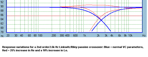
To shed some light on whether the observed effect was due to voice coil heating or changes in the voice coil inductance with increasing excursion, as discussed at Madisound, I perfromed some simulations using SoundEasy. These results are shown in the 3rd figure. The blue curve represents the electrical response of the tested crossover loaded by "normal" voice coil parameters, Re and Le. The red curve is the response with Re increase by 25% which would be equivalent to a 60 degree C temperature rise. The green curve reperesent the response with a 10% increase in Le. Obviously, in this case the increase in Le seems to coincide more closely with the observed measurements.
Similar simulations were perfromed using a model of a tweeter's impedance. The results for the tweeter model are shown in the 4th figure. The model did not include the impedance peak at the tweeter resoance and the voice coil and Le was compensated for using a Zoble. Re was taken as 6 ohms and Le 0.05mh. Here we see that there is very little effect due to changing the value of Le by 10% (green curve) but there is a significant due to a 25% increase in Re (red curve). This is not unexpected since changes in Le would affect the impedance at high frequency more than in the crossover region.
Thus it would appear that for a woofer or midrange there are detrimental effect due to both heating and increases in Le where as for a tweeter the dominate effect appears to be heating.
The last figue show the modeled effects of both increases in Re and Le due to heating and excursion for a 2nd Linkwitz/Riley crossover at 2.5k Hz. In the simulation the woofer was assumed to have Re = 6 ohms and Le = 0.5mh. The tweeter had Re = 6 ohms and Le = 0.05mh. Both drivers were compensated by Zobels to yield pure 6 ohm resistive loads ubbder normal conditions. The red curves show the total effect of increaseing Re by 25% and Le by 10%. |
|

|
|
|
|
|
|
|
|
|
|
 |
|
|
|
|
|
 |
|
|
|
|
|
 |
|
|
|
|
|
|
Other topologies will behave differently but these results and simulations show that it is very important to consider the impedance characteristics of the drivers with varing signal level when designing a crossover, and it is important to consider the intended play back level in the design processs. It could be argued that the results presented here favor the use of active crossovers since the transfer functions would not be affected by variations in driver impedance levels with increased signal level. However, it should be noted that the response irregularities with signal level shown here are in the imediate region of the crossover. Typically in a two or three way system the crossover tot he tweeter is in the 2k Hz to 4k Hz region where the ear is extremely sensitive, particularly at lower SPL levels. Thus designing a crossover with a so called BBC dip observed in low level measurements may tend to flatten out at elevated SPL levels where the ear is less sensitive in this critical area. Thus there is the potential for the behavior show here to actually be used to advantage in passive crossover design in an effort to retain tonal balance as the playback SPL level varies. Regardless of whether or not such benefits can be realized, the important observation here is that the designer must be cognizant of these effect if the crossover design is to proove sucessful. |
|


