| Time aligned, Phase coherent, Phase aligned, Transient accurate, What's up with that. |
 |
 |
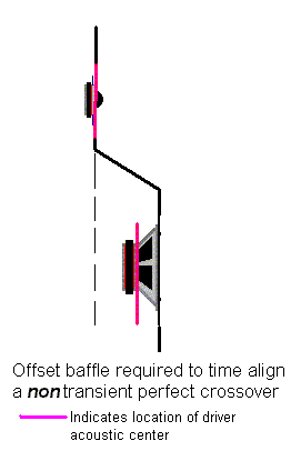 |
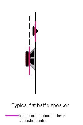
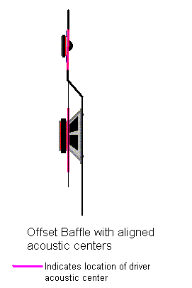
| Below are 3 different baffle layout that are typically used in convension loudspeakers. The first figure to the left shows a flat baffle. As is apparent, this layout generally results in a relative offset between the woofer an the tweeter in which the AC of the woofer is located behind that of the tweeter. This is a very common layout, but it will not allow time or phase alignments when using any of the standard crossovers (unless some other means is used to account for the non zero relative offset). The center figure represents a layout in which the ACs of the drivers lie in the same plane. There is no relative offset between the woofer and the tweeter in this case. Time aligned, phase coherent, phase aligned and true transient accurate crossovers can be developed with this configuration. Finally, the figure to the right shows a layout where the tweeter AC is located behind that of the woofer. This layout is typically used with non standard time aligned crossovers. |
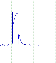
| If we restrict our discussion to the standard crossovers for the moment, we know that, provided the acoustic output of the woofer and tweeter match the target functions for the crossover filters in question, the resulting system will have flat summed frequency response only if the drivers are mounted in accordance with the center baffle figure, with aligned ACs. But what will the transient response of the different standard crossovers look like? A what is the effect on the system if a flat baffle is used? To answer this, lets look at a series of simulated results for impulse and step response for the standard crossovers from 1st order to 4th order. We consider results for a flat baffle with a relative woofer offset of 30 mm, and the offset baffle with aligned ACs. In all cases the impulse response is was for a 0.5msec wide pulse. |
 |
 |
 |
 |
 |
 |
 |
 |
 |
 |
 |
 |
 |
 |
 |
 |
 |
 |
 |
 |
 |
 |
 |
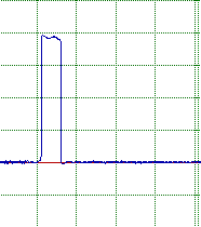
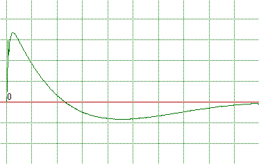
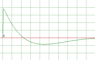
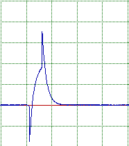
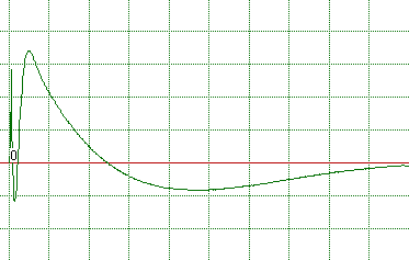
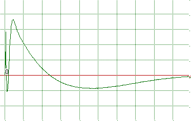
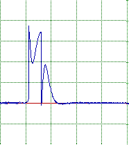
| The figure at the left shows the the response of a 1st order crossover to a 0.5msec impulse when the drivers are mounted on flat baffle. The distortion of the impulse is due primarily to the missalignment of the drivers ACs when using a flat baffle. The figure to the right shows the result when the ACs are aligned. The slight distortion is due to the low frequency limit of the system which was modeled as 2nd order at 40 Hz. Below the impulse response figures are the corrisponding step responses. The 1st order crossover is a true phase coherent, transient perfect crossover which is time aligned when there is no relative offset of the driver ACs. |
| 1st order Butterworth |
| 2nd order LR |
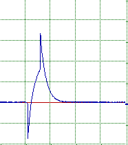
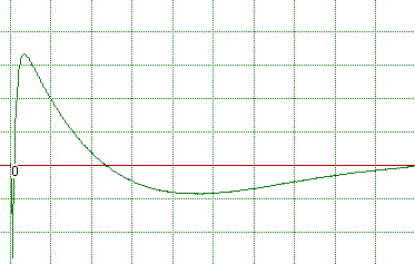
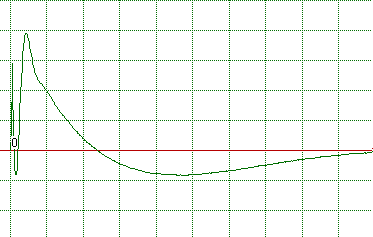
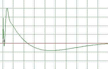
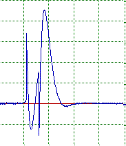
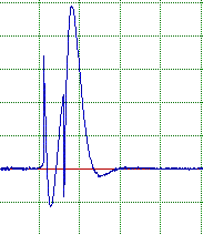
| This set of figures corrisponds to the 2nd order LR crossover. Note the extreme distortion of the impulse response regardless of whether or not the ACs are aligned. While the LR crossover requires the ACs to be aligned if the response is to sum flat, it also required that one driver, the tweeter in this case, be connected with reversed polarity. Thus, aside from other transient problems, the tweeter is firing in the wrong direction. With the drivers mounted with no relative offset between the ACs the 2nd order LR crossover could be considered a phase aligned crossover, but it falls short of time alignment, phase coherence, or transient perfect. The step response at first looks reasoable, but then we notice the initial negative tweeter spike. Even so, the step response is better than that of the higher order crossovers considered below. |
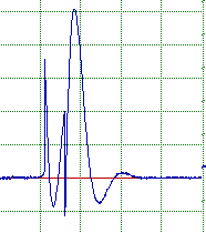
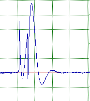
| These four figures corrispond to the 3rd order Butterworth crossover with both drivers connected with positive polarity. Both the impulse and step response are clearly distotred. The step response shows that there is sufficient delay introduced by the crossover so that the response of each driver is individually apparent. The fact that there is little difference between the flat baffle and the case where the driver ACs are aligned is an indication that the crossover introduces more delay than that represented by the 30mm relative offset in the missaligned case (also true for the 2nd O LR). As with the 2nd order LR, with the ACs aligned this crossover is phase aligned (to the design target), but nothing more. |
| 3rd order Butterworth |
| 4th order LR |
| These figures corrispond to the 4th order Linkwitz Riley crossover with both drivers connected with positive polarity. As with the 3rd order Butterworth case the impulse and step response are clearly distotred. The step response again shows that there is sufficient delay introduced by the crossover so that the response of each driver is individually apparent. The little difference between the flat baffle and the case where the driver ACs are aligned again indicates that the crossover introduces more delay than that represented by the 30mm relative offset in the missaligned case As with the 2nd order LR, and the 3rd order Buttwerworth with the ACs aligned this crossover is phase aligned (to the design target), but nothing more. |
| This series of 6 figures represents the result for a non standard crossover on a flat baffle (left), with aligned ACs (center) and with the tweeter AC behind the woofer's (right). In this case the crossover uses a 2nd order Bessle low pass filter target function for the woofer and a 1st order high pass target for the tweeter. The left most figure represents the result for the impulse or step response when the tweeter AC is positioned behind the woofer's in a manner that optimizes the impulse and step response. The overall system is then optimized for flattes response. This is a time aligned system. It is neither phase coherent nor transient accurate, however it does approximate these types of system closely. In theory, there is no driver position that will yield perfectly flat response of the system but, as is shown below, supprisingly flat response can be obtained. Clearly we can see the improvement in the step and impulse response as the tweeter position is moved. In the left figure the tweeter AC is 30 mm behind the woofer's. |
This system works as well as it does because the Bessel low pass response has a constant delay in its pass band. Thus by positioning the tweeter such that the additional propagation delay to the design point matches the delay introduced by the Bessel response of the woofer. Since the 1st order high pass tweeter response does not have constant delay, the sistem is not completely linear phase or phase coherent. |
| Mixed, 2nd order Bessel low pass, 1st order high pass |
| The figures above show the transient characteristics of the different crossover with differen driver alignments. However, we should look at the effect of driver alignment on the system frequency response as well. Recall that for the standard crossovers the system response will be flat when the driver's AACs are aligned (center baffle). But what is the effect of using the flat baffle, and what does the response of the last, non standard crossover look like? The figure to the left shows the response of the standard crossover with the drivers mounted on a flat baffle. As can be seen, the 1st and 3rd order Butterworth crossovers are subject to the most significant variation in frequency response due to driver missalignment. The 2nd and 4th order LR filters show relative insensitivity to the missalignment. This insensitivity to missalignment is one reason for the popularity of the LR crossovers.However, the reversed polarity null seen with these filters will move off axis as a result of the missalignment. The lower 3 curves show the response of the Bessel/1st order time aligned crossover for the three different baffles. Note that the response is quite acceptable when optimized with the drivers in the time aligned position. |
| Hopefully this brief discussion will help bring a better understanding to the various terms that have been addressed and will help further the understanding of the transient response characteristis of the various standard crossover. Additionally, while if is often believed that only 1st order crossovers can acheive true transient accuracy and phase coherence, there are an infinite number of possible crossovers of varing order that can accomplish this. On my main web page you will find 2 such examples, the B&O filler driver concept, and my own 2nd order transient perfect crossover design. Many other such transient perfect crossover designs may be found in the literature. I would also like to point out that the simulated results presented here are simply a result of the underlying physics of each crossover design and are not to be taken as criticisims or endorsements of any given design. There are many other factors besides transient response that go into making a selection of one crossover over another. For example, power response and lobing behavior may also play important roll in the design. As always, a series of comproimises must be made by the designer. |