| PLL 5080 |
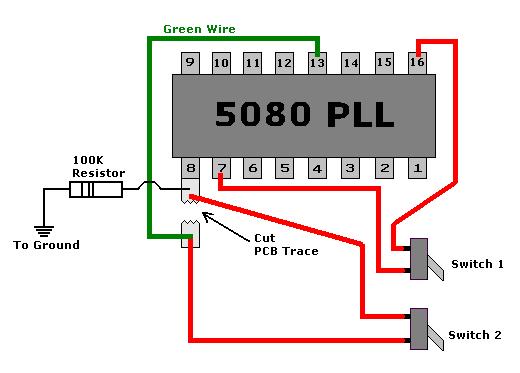 |
| 1) Install 2 SPST toggle switches on the radio. 2) Unsolder the green wire thats attached to pin 8 of the PLL. 3) Cut the trace that goes to pin 8 of the PLL. 4) Resolder the green wire to the side of the trace that doesn't touch pin 8 of the PLL. 5) Solder a 100k resistor from pin 8 of the PLL to PCB ground. 6) Solder all the wires from the 2 switches to the PLL as shown above. With both switches down, you'll have regular CB channels With switch 1 up and switch 2 up, you'll have lower channels 3 - 26.665 4 - 26.685 5 - 26.695 6 - 26.705 7 - 26.715 8 - 26.735 9 - 26.745 11 - 26.765 12 - 26.785 13 - 26.795 14 - 26.805 15 - 26.815 16 - 26.835 17 - 26.845 18 - 26.855 19 - 26.865 20 - 26.885 22 - 26.905 23 - 26.935 24 - 26.915 25 - 26.925 26 - 26.945 With switch 1 up and switch 2 down, you'll have the upper channels 11 - 27.405 12 - 27.425 13 - 27.435 14 - 27.445 15 - 27.455 16 - 27.475 17 - 27.485 18 - 27.495 19 - 27.505 20 - 27.525 21 - 27.535 22 - 27.545 23 - 27.575 24 - 27.555 25 - 27.565 26 - 27.585 |

|