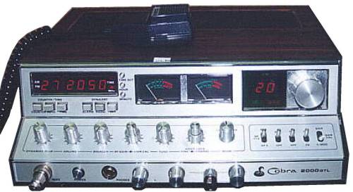
| 2000 GTL |
 |
| Power Modification 1) Remove TR24 2) Remove R126 and replace it with a 2.2k resistor 3) Remove R124 and replace it with a 4.7k resistor 4) Re-tune coils L37 and L38 for maximum forward power VR1 AM Signal Meter VR2 SSB Signal Meter VR3 Squelch VR4 Carrier Balance VR5 TX Frequency VR6 TX Meter VR7 Modulation Meter VR8 Final Bias VR9 Driver Bias VR10 AM Power VR11 SSB Power VR12 Modulation (you can cut R131 to bypass this completly) Clarifier Modification 1) Cut R44 and D52. 2) Remove R174 and place a jumper in its spot. 3) Follow the Yellow wire on the back of the clarifier knob down to the PCB board. Unsolder it from the board. Resolder it to PCB ground. 4) Follow the Red wire on the back of the clarifier knob down to the PCB board. Unsolder it from the board. Resolder it to pin 3 on the MB3756 IC chip. 5) Cut the Brown wire on the clarifier knob. You'll have about 6khz of slide. |