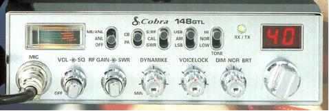
| Cobra 148 GTL |
| Power Tweek and Modulation 1) Change R126 to a 2.2k ohm resister. 2) Change R124 to a 4.7k ohm resister. 3) Remove TR24 4) Re-tune L37 and L38 for maximum forward AM power. 5) Adjust VR10 for maximum PEP on AM. 6) Adjust VR11 for maximum PEP on SSB. I do not recommend cutting R131 which limits the modulation. If you "clip" or remove R131, you'll have increased modulation on AM, but severe "garble" on SSB. I recommend getting a good aftermarket powermike. You can also adjust VR7 for a little increase in modulation, but watch it on SSB. Extra Channels Find the MB8719 PLL chip. Wire a SPST switch from pin 10 to ground. Wire another SPST switch from pin 11 to pin 12.( Sorry, I don't have a channel map as of yet.) If you don't want to "Hack" your radio up, you can use the ch9-19 switch and the NB/ANL switch. Just remember to solder jumper wires on the NB/ANL to engage those functions. Unlocking the Clarifier 1) Clip one end of R44 and D52. 2) Remove R174 and solder a jumper wire in its place. 3) Locate the Red wire from the clarifier control and follow it to where it connects to the main PC board. 4) De-solder this wire and resolder to the circuit board ground. 5) Locate the Orange wire from the clarifier control and follow it to where it connects to the main PC board. 6) Desolder it from the board and resolder to pin 3 on IC-4. Let the radio "sit" for about 2 hours, with the clarifier knob set at "12-oclock" to get used to the new modification. This will give you about 6 kz of slide.(1kz up- 5kz down) Variable Alignments VR1 AM "S" Meter VR2 SSB "TRX" Meter VR3 Squelch VR4 Carrier Balance VR5 "TRX" Frequency VR6 RF "TRX" Frequency VR7 Modulation "AMC" VR8 Final Bias VR9 Driver Bias VR10 AM Power VR11 SSB "ALC" |
 |