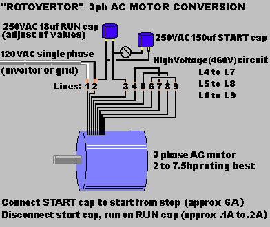
One inch thick, 12" wide, polyethelyne (cutting board plastic) rotor with 32 alternating north-south magnets pressed into it attached to 5hp AC motor's shaft:
Backside of plastic ring containing 13 coils spaced evenly attached to 5hp AC motor frame:
Air gap between rotor magnets and stator coils:
13 generator coils attached to housing of 5hp AC motor modified to "RV" operation.
"RV" stands for "rotoverter"...a simple AC motor power-saving conversion which is an invention of Hector Torres of Puerto Rico. Very basically it means to modify a large AC motor connected up to its 460V high voltage circuit and instead runs on 120Vac grid power (or invertor)...also variabel voltage devices can be used to run it too.
The rotorvertor system runs also on only two phases of the three phases it was originally designed to operate on...also it is tuned to very low current draw via AC capacitors between phases 2 and the "uin connected" phase 3. (study circuit diagram shown)
The late Bill Muller of Penticton, Canada is the one who showed me how to build super-effecient magnetic rotor generator/alternators using neodymium magnets in the rotor and odd-even configuration of coils and magnets.
This "overunity" (more watts out than in) motor-generator project is a combination of information and designs from both Bill Muller and Hector Torres. (the "Muller-RV")
TO CONNECT:
The white wire from the house power connects to line labeled #1 of the AC motor connections, the black wire on line #2.
There will need to be a "START" and a "RUN" AC cap between the 2nd and 3rd (blank) line/phase...connect the motor to 460V circuit for lowest possible impedance and amp draw, and adjust RUN cap uf size ("TUNING") for lowest possible draw while turning load.
The particular 5hp motor shown in the photos starts up with a 250V/150uf START cap, then the START cap is disconnected when motor gets up to speed and then runs on the 250V/18uf RUN cap only...these modifications will drop the watts the mtoor draws at idle, to approx 20 watts.
Drawing of the RV circuit:
In this particular prototype shown, the 13 coils mounted around the rotor-disc of magnets are wound with 18ga wire to .7 ohms impedance each, (approx 120ft of wire) the coils are wrapped around a ferrite-tube core. Improvenments on this design would be low-hysterisis cores, such as metglas or amorphous black sand, and coils made of "litz" wire - which is a type of magnetic wire ususally used in high frequency devices (multiple paralell strands of very thin magnetic wire).
Improvements on the design shown here would be a variable voltage-feed, (besides just 120Vac) and also adjustment of the frequency of the AC power feed (besides jsut 60hz) and finally a pulse-width control too of the AC phases. ("advanced rotovertor")
Look at "circuit diagrams" link for circuit that makes the rotovertor motor be a batery-charging system as the motor runs...this makes for "overunity" operation since you can rock the charge and run battery stacks back and forth as you take power off the Muller genrator on the shaft of the motor.
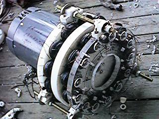
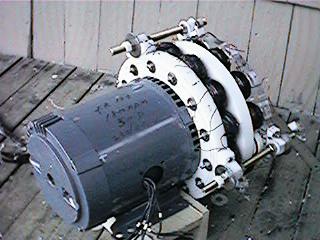
The complete motor-generator with both coil-plates installed for 26 coils total:
Another view:
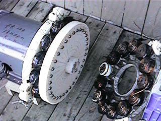
End coil-plate removed to show 13 coils and 32 magnet rotor: