Cursor blocks settings of scope in all photos below are at 5V vertical and 1 millisecond horizontal.
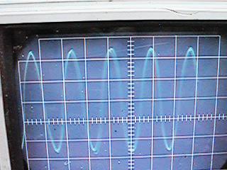
In first photo is the AC sine wave of a single generator coil with scope leads across the coil.
This signal is produced with 32 alternating N-S neodymium magnets spinning past it at 1800rpm.
Note that in this photo, the center of the sine wave happens to be near the 5V cursor line.
An AC meter will read 13.5Vac while the scope form will look like this:
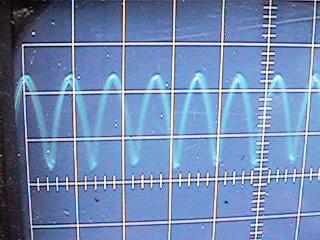
All settings on the scope are the same as above, but now it is DC voltage after coil leads go through a full-wave bridge rectifier.
A DC meter will read 13.5Vdc while the scope will look like this:
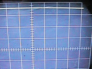
Below, the scope has been re-set so that the meter will show same voltage as on scope; and now a 15uf tantalum capacitor also is across the DC output which smooths the signal into a straight DC signal:
A DC meter now will read 18.1Vdc while the scope shows this straight line:
Note:
With a resitor load of 10 ohms connected across the DC cap, the volts will drop to 7.8 VDC and there will be simultaneously .77AmpsDC on an ammeter in line to the resistor.
So this means real power (actual watts) produced by a single coil in this "RV Muller" motor generator system with these type of coils and cores will produce approx 6watts.>br>
(7.8Vdc X .77Adc = 6.006 Watts with that 10 ohm resistive load)
UPDATE:
I did further testing, and found LITZ type coils, which are coils wound with 8 or more very thin paralell winds (36GA wire in this case) produced X3 more voltage than the thicker 18GA wire shown in photos here.
The increased power is because LITZ magnetic wire in coils is superior to thick solid wire in high frequency operation, and with a rotor of 32 magnets spinning past a coil at 1800rpm, this system is operating in high frequencies.