April 8, 2004
|
 |
Yes folks, the apocolypse draws near. I am using wheels. After nearly
suffering a mental breakdown constructing my last walking robot (there's
no build page yet on that one sorry), I felt that it was time to design
something a little less draining. It was not easy to accept these strange
round things everyone else seems to use, so to soften the blow I decided
to use "Omni" wheels. I first saw these cool devices on Tony
Hall's "Y Chromosome".
For months I stared at them, fascinated by the ability to move in every
direction. To that end I designed "Skittlebraü" an Omni
wheeled 12lb robot. Of course for a weapon it has something spinny, and
as it's invertable as well.
|
 |
To begin with I needed to choose the correct
omni wheels. For those unfamiliar with this type of wheel it consists of
a driven (or in some situations undriven) hub with rollers on the periphery
that rotate at 90 degrees to the hubs axis of rotation. While being driven
in one direction the omni can roll in the perpendicular direction. With
a minimum of three omni wheels you can make a robot base translate in any
direction, forward, backwards, and sideways without turning first. It is
my hope that this increased freedom of motion will be both entertaining
as well as effective in combat.
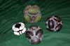
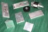
I had originally planned to make my own wheels, as it is certainly within
my capability to do so, however I figured it might be worth the time to
purchase ready made options, at least to begin with. On the left is an all
acetal plastic omni with 8 rollers. While it rolls great, the hard plastic
rollers lack traction, making it hard to drive. The rear green rollered
wheel is huge, ~3.5" in diameter, and rather heavy. It does, however,
sport a urethane roller which provides superior traction. The black rollered
wheels in the foreground are just right. They also have urethane rollers,
but are a much more manageable ~2.375". Available from www.acroname.com
they aren't the cheapest, but are just what I needed. |
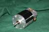 |
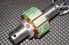
The motors I selected for drive are these, the
so called "Masek Mystery Motor". I happened to have a couple lying
around, and they love high voltages, perfect for this project. They also
have 4 brushes and a relatively high torque/low rpm, making them well suited
for minimalist reduction techniques. |
 |
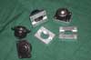
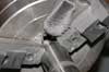
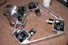
Here are the parts which make up an individual
drive "pod". There are three in total, spaced 120 degrees from
each other. Some of these will be pocketed a bit further for increased weight
savings. A simple single stage belt reduction with 3mm pitch HTD belts (www.sdp-si.com)
reduces the RPM to an acceptable range. Missing from this shot are the belt
and keyed shafting. |
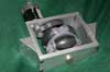 |
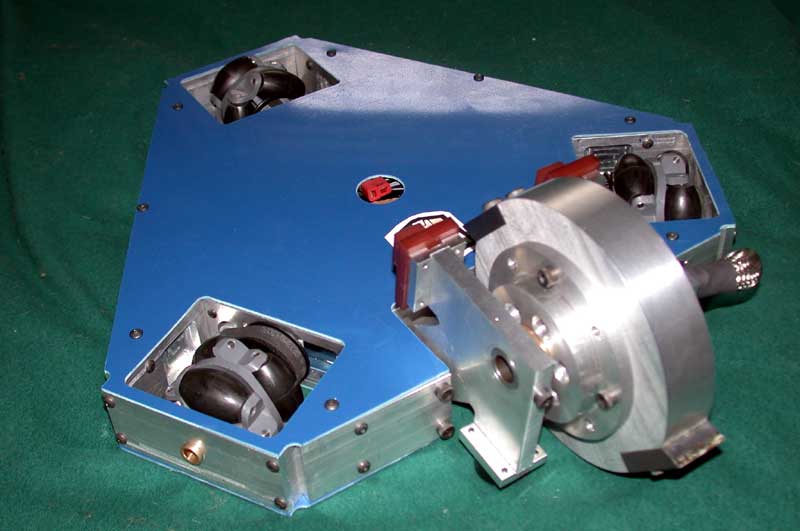
A shot of the gearbox assembled. The angled side
blocks allow the frame rails to be machined flat, instead of making them
at an angle. |
 |
Multiply the above times 3 and add side rails.
One of these side rails will be replaced later with the one that will mount
the weapon, but I wanted to drive test before I had completed the weapon.
Plus it never hurts to have a spare frame rail. |
April 15, 2004
|
 |
A bunch of stuff came in this week, and a good thing too as the comp
is a few short weeks away. Although my mill is quite useful, it's steel
handling capabilities leave a little to be desired. I could have
done them myself, but after considering having to source the appropriate
alloy, machine it, and then properly heat treat it, I decided to just
have terry from Team Whyachi
make these for me. He did an excellent job, exactly as per my specs, and
a very reasonable price. Can't wait to get the rest of the weapon done
to try them out!
|
 |
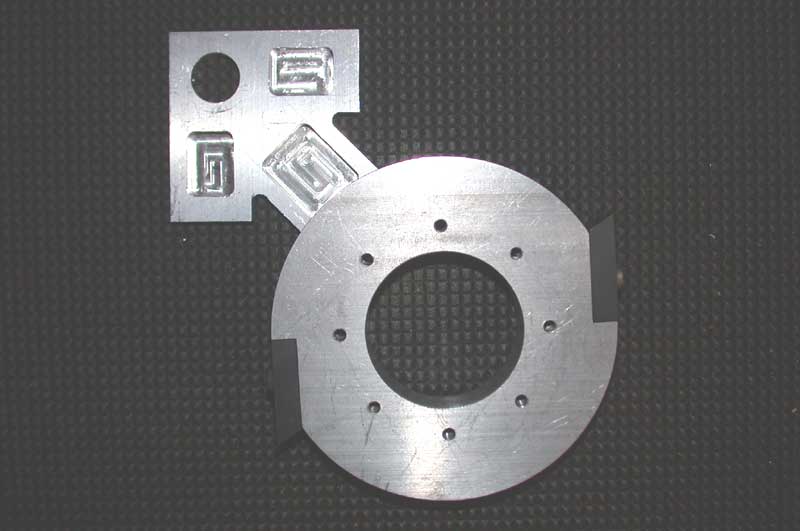
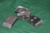
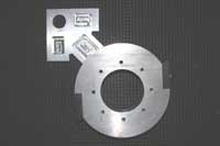
I spent a morning this week working on these as
well. They are mounts to hold the ball casters (from perpetual fav McMaster).
Sadly there are no small stem mount ball casters within a reasonable price
range. These plates allow me to mount up the $3 cheap versions to the weapon
standoff plates. |
April 16, 2004
|
 |
Up until now everything for this bot has been
fairly uncomplicated, totally against everything we stand for at Team Nar.
Thankfully the weapon provides ample opportunity to overcomplicate things.
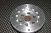
Pictured here is the worlds most machined ashtray....No, not really. This
is one of two weapon hubs. The other one does not contain the series of
12 notches around it's perimeter. This is the interior of the weapon hub. |
 |
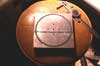
I didn't spend the hour precisely cutting those
notches for no reason. For those unfamiliar with it, the part to be machined
is mounted in a rotary table, which allows the part to be rotated a specific
ammount. With it you can make all sorts of interesting things, from precise
hole patterns, gears. to little castle like notches like in this part. The
hub above was made in the same way. This particular rotary table has an
attachment so the lathe chuck screws directly to it, making it easy to transfer
round work back and forth from the lathe to the mill without rechucking.
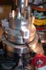
The part shown here is the magnet ring. Made of magnetically soft iron,
it cannot be magnetized like a piece of steel can. It's purpose is to direct
the magnetic flux back into the motor. The reason for the notches will become
clear as the entire weapon is shown. I wanted to make the weapon as easy
to disassemble as possible with a minimum of gluing. The notches aid in
this. |
April 18, 2004
|
 |
The last time motor I built, I relied on making
thin plastic spacers to hold the magnets apart as they are glued into the
ring. Adjacent magnets have opposite poles, therefore they snap together,
making the chore of gluing them in and maintaing spacing very dicey to say
the least. My plan this time is to make space rings, to hold the magnets
at an even spacing, and then glue the ring itself. A piece of thin plate
is clamped to the rotary and the fun begins. The first series of cuts opens
the center of the ring. A spreadsheet was done beforehand to make a table
of the angle to cut each "tooth" in the ring at. The last cut
around the outside frees the ring from the plate. |
 |
Here are the rings in their intended use. Not
all the magnets are shown here, these are some old ones I had from my last
order, the new ones should get here later this week. 14 will go in the ring
in total. I got these from Amazing
Magnets. They are composed of Neodymium, some of the strongest magnets
that you can buy. |
 |
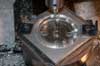
I couldn't resist taking this shot. The motor
axle is a piece of 3/4" DOM tube, which although really strong, wasn't
precisely the right size. Taking cuts on the lathe with a tool bit is kind
of difficult for the tiny ammount of material I had to remove, so strips
of emery cloth were used to sand off a couple of thou's and polish things
up in the process. Since I'd played this game before, I knew full well that
inhaling nostrils full of steel dust is no fun at all. My solution was to
put one of the Neodymium magents on the steel body of the chuck, what you
see here is the metal "fuzz" caused by the magnet attracting all
the tiny bits of steel that came off of the shaft. |
April 22, 2004 : The motor IS the weapon...
|
| |
Ok, time for a bit of discussion here. I've kinda
kept quiet about the weapon concept for this bot, although the general idea
has been out there (brushless, spinning disc, etc.) the full scope has not
quite been revealed. For this project I wanted to do something a little
different than the standard "motor through a reduction to a spinning
mass" deal. It's not the most efficient design for a number of reasons,
notably losses in the reduction, and the typically essentially useless mass
in the center of the disc, which contributes little to MOI for it's weight.
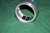
The solution I found eliminates both the reduction, and the center useless
mass. The weapon motor IS the spinning disc. The disc itself is dounut shaped
(see, you are never too far away from the Simpsons, mmmm donut). The magnet
ring fits into the hole in the donut and is keyed into one of the disc hubs,
preventing it from moving relative to the disc. The other hub provides further
support, as well as preventing the ring from slipping out. The motor armature
sits on the shaft between the two hubs. But wait, how do I get wires to
the armature with hubs on either side? Simple, just use a hollow shaft,
and run the wires through it and out the other side.
Now, with all that out of the way, lets get on to the construction... |
 |
I wanted to make the disc out of 1" thick
stock, which is not the easiest thing to cut, and I don't have a metal cutting
bandsaw (or a bandsaw of any kind for that matter). The local metal shop
was happy to chop me off a chunk of 1" bar stock, but wasn't about
to cut any circles, and a piece of round stock would be impossible to work
with, as I have no chuck that can grip something that big in order to get
the faces parallel. Using bar stock makes the faces parallel, and then I
used this technique, known as "Gang Drilling" to begin the cutting
process. Using CAD, I layed out a series of holes, that came very close
to intesecting with each other. Taking a printout of these, I punched the
center locations and drilled them on the drill press. By the time this was
done, the miniscule ammount of metal that was left was cut easily by my
scroll saw!! While this method certainly takes some time, I'd much rather
let the drill press do the work, than me with a hacksaw, plus the accuracy
of this method is much better.
The four holes in the center allow me to fasten the piece to the rotary
table. A couple of passes round the outside cleaned up the rough edges,
and brought the disc to the correct size. |
 |
This has to be my favorite setup of the whole
project. This is to cut the pockets that hold the teeth. To begin with the
inside of the pocket needs to be a right angle, thus making it impossible
to use the milling cutter from the top, as this would leave a radiused inner
corner. Also the holes that hold the teeth on must be drilled into the surface
of the pocket. To do both of these things, the head of the mill is tipped
90 degrees. To make up for the height lost in this fashion the whole rotary
table must be raised ~1.5", you can see the big piece of Al round that
I keep around for this purpose. If I didn't do this, the cutter could barely
reach the top surface of the disc, let alone cut across it. |
April 26, 2004
|
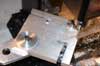 |
The weapon will be held off the ground using these
weapon standoff pieces. The 90 degree stuff was easy to mill with the part
clamped square to the table, but how to do the 45 stuff without all sorts
of hastle and aligning the rotary? Since the pivot axle and weapon axle
holes line up on the 45 deg axis, plugs were cut to fit tightly, and holes
tapped into a scrap bar. The vise at 90 provides all the hold I needed.
|
 |
Here is the completed weapon armature. I used
an armature core from another motor and took all the wire off. It was wound
stock in a completely different manner than I wished to use in this project.
The 3/4" DOM tube shaft was sanded ever so slightly in the lathe to
fit, and holes were drilled to let the wires pass through the center of
the shaft. The aluminum collar seen on the left prevents lateral and radial
motion on the shaft, and 4 screws secure the pole plates to this collar.
The holes at the ends secure the shaft between the two standoff plates. |
 |
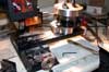
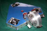
A little bit of pocketing to save some weight,
and the frame is assembled. Note the coffee cup for scale and santity. All
it needs now are the top and bottom covers, and to be wired. Not shown here,
but worthy of note is the manner I used to cut those covers. They are made
from garolite, which is very hard on standard HSS tooling, and I have nothing
big enough to cut them with anyway. I printed a sheet of paper with the
bolt hole pattern on it and drilled them. I then bolted the sheet to the
frame, and used a laminate trim bit (a straight flute bit with a ball bearing
on it to follow the contour of the aluminum) in a router, to cut the plates
exactly the size of the frame. The carbide router bit did a good job. |
April 30, 2004
|
| No time to talk, I finished on time, fought tooth
and nail for the last couple oz. First pic is some of the weapon parts,
when the bot is dead, I'll fasten them togther like that and wear them around
like Mrs. T. Second is all done! |
 |
 |
May 1, 2004
|
|
Skittlebraü did great at it's first competiton. Following is a brief
summary :
First round was against Tyrant. In an unforseen design oversight, the
weapon motor had so much torque that it would kick downward into the floor,
stalling the blade on startup, and putting the controller into a protective
reset. After the reset I would try again, but to no avail. Al's blade
actually caused some damage, and when he sliced my weapon wires, I tapped
out.
A little last minute work in the schools machine shop (Big thanks Daniel!)
and we locked the weapon pod from pivoting. A gamble to be sure, but at
this point, giving up invertability was of little consequence if I couldn't
use the weapon while upright! This fight was against Sir Nuts And Bolts.
Alex put a couple of decent gashes in my disc, before I flipped him, there
is some great video of this fight below.
Next up was Turkish Twist. Couple of shots and he wound up in the bumper,
and a need side strafe move flipped him. Video of this fight is below
as well.
The fourth fight was agains Glen's Running with Scissors, a truly unique
design. The robot actually pivots around the center axis opening and closing
the front blades, like a pair of scissors. Way cool use of the ever present
"Power Wheels" gearboxes! Glen told me later that he did what
his son Vinny always told him not to do, and was not aggressive.
I removed a couple of parts, and "flattened" a wheel before
Glen tapped out. Great fight, video of this one can be found below as
well.
Dizzy Dragon, one of the bots I was frightened of coming into the comp
was my next fight. As it turns out his weapon was damaged in the previous
rounds, so there was little to fear in the way of damage. We crashed around
for a bit, and eventually his BEC wire came loose.
It seems many people at the comp were waiting for this next one. I personally
could have done without it, although it was a good fight. This one was
against Alos, 12PoP Champion. In the beginning I was able to pop him into
the air, and stay fairly well out of reach of the weapon. Some crutial
driving mistakes allowed him to get the drum under me, and he shattered
an omni housing, causing a couple of the rollers to drop out. Somewhere
around this time, the drive motor screws came loose, allowing the belts
to slip, and me not to be able to drive. I tapped out. It went better
than I expected overall, not an insane ammount of damage, with any luck
I'll get him next time!
Skittlebraü took 4th place overall, a very good showing for one
of my robots, and certainly respectable for a robot on it's first time
out. Many things were learned, and many improvements are planned
|
May 4, 2004
|
|
Videos Are UP! Thanks to Rob and Pound of Pain for hosting these, as
my meager web site does not posses the file size to do so. Right click
on the link and select "Save As" to get them onto your hard
drive. Enjoy.
http://www.poundofpain.com/video/Skittlebrau_Vs_Running_With_Scissors.wmv
http://www.poundofpain.com/video/Skittlebrau_Vs_Turkish_Twist.wmv
http://www.poundofpain.com/video/Skittlebrau_Vs_Sir_Nuts_And_Bolts.wmv
|