Belladonna v2.0
March 25-26, 2003 |
|
| This weekend Jr of Team Mad Cow and I took a little ride up to Holland, N.Y. (just outside of Buffalo) to go visit the shop of CNCbotparts.com. Gregg Verbeck is a super cool guy, and his shop is downright amazing. I really love it when the exact correct tool is available instead of having to hunt for a stop-gap solution. He's also WAY more precise than I am used to. He actually asked me if it was alright to have a hole .001" oversized, usually if I'm withing 5 I call it close enough. | |
 |
First up were the motors. They
are made to be sealed motors, which works well for outdoor use, however
this doesn't allow any air circulation within the motor can. We have found
that the motors get super hot during competition, so here are a couple
of things we did to remedy the problem. Step one was to take the insulating epoxy coating off the outside of the can. As long as I had it in the lathe I figured I could take off a couple of thousandths out of the metal as well. The blue tubes on the right are the nozzles of a "Cold Gun" which cools air by some sort of vortex action, giving you a dry blast of coolant. They were used to keep the motor can cool to prevent demagnetization of the magnets (magnets + heat = no more magnet). |
 |
Next step was to open up a little slot in the side of the motor. Nothing like a huge CNC mill to do it. Man do I love that thing. |
 |
A quick trip to the deburring wheel, and a little pollishing and we are done. Although I still want to get some heavier wires, and open up the front end a bit, this is pretty much it. |
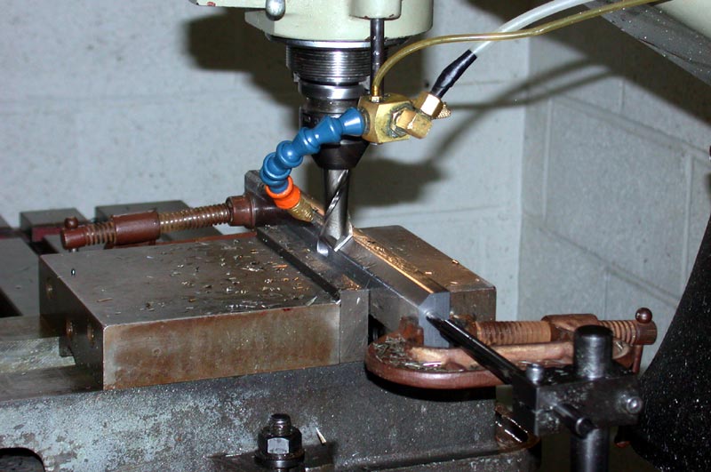 |
Did I mention I love this mill? After bandsawing and squaring the 4340 (Thanks Wayne!) we start to take some meat off the edge |
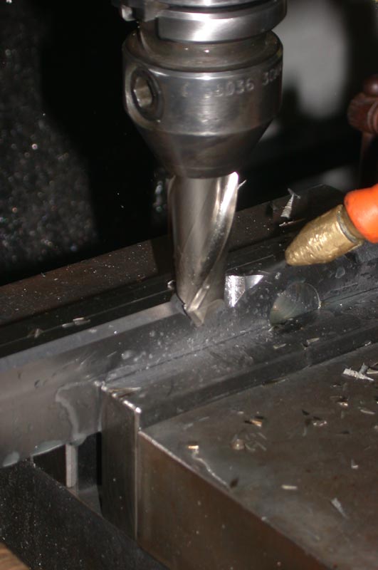 |
A closeup shot of the huge chamfering cutter in action. |
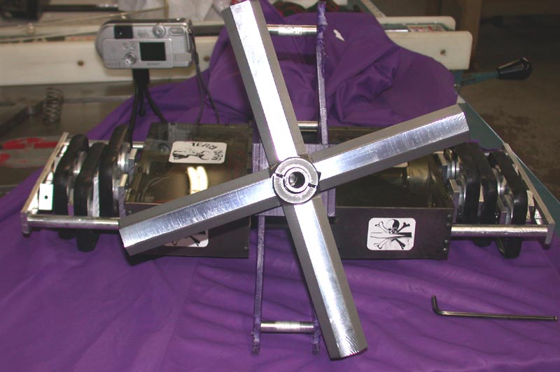 |
The finished set of blades. Aside from a little heat treating this is what you are gonna see. Oh yeah I guess there are two now instead of the old single blade. I managed to ditch a lot of weight from the overdesigned cam system, and removing the Rx battery (for Fuzzy's) and the weight loss in the motor allowed me to fit in another one. Good deal! |
May 22, 2003 |
|
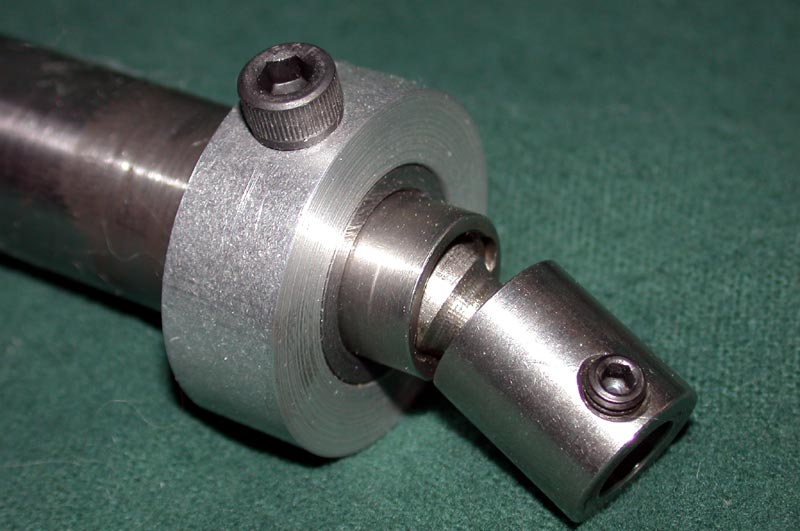 |
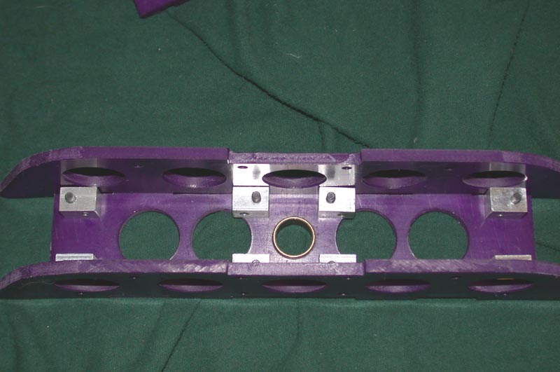
Once again I needed to rebuild the weapon module (sooner or later I am bound to get it right). There were several issues to be resolved, I started with the coupling. The old coupling didn't allow for misalignment in every axis, so there was a bit of binding. This miniature ball coupling from SDP-SI was just what I needed. As you can see in the pitcure, the bolt goes through the shaft collar (to prevent the shaft from flying forward), through the shaft, and into the threaded hole in the coupling itself. The other end secures to the motor shaft. Despite the relatively high cost of this part, it seems to be worth it, as it can handle relatively high parallel, angular and even axial misalignment, while operating at 10k rpm, and a reasonably high torque figure as well. |
 |
The final mods to the weapon motor. Unfortunately you can't see it in this picture, but there are now ball bearings in the motor. I got hold of a couple of ABEC 3 bearings from Walmart that were made for rollerblades. They fit the shaft perfectly but the recesses in the end caps needed to be bored to handle the width and depth. Works like a champ and seems to have dropped the no load current down a couple notches, as well as reducing heat in the motor (always a plus). The final mod was to chop a little off of the shaft, as the coupling needed some more space than the other one did. |
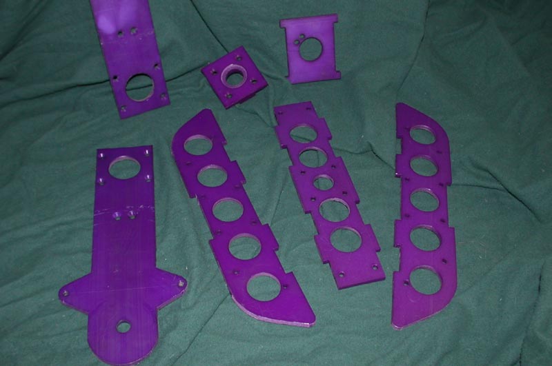 |
Your standard dyed UHMW weapon parts. Of note here are the thicker small block which is the back bearing support. It was made like this to allow for more clearance on the coupler. Next to it is the rear motor support. It holds the back of the motor and prevents it from flopping around, causing problems with the shaft geometry. |
 |
I have heard from a couple of people that they wanted to use UHMW as a frame member because it is cheap, light and doesn't crack. They always wind up saying they will attach it by edge tapping the parts. This is my solution which I think is a just a little stronger. Clear holes are drilled through the UHMW and 10-32 screws are tapped into the aluminum blocks at right angles. This method of fastening has yet to fail me in combat. |
 |
Detail of the front plate. It was added to increase stiffness in the two uprights. In addition to the aluminum blocks seen above the UHMW itself was milled to form what is known as a "finger" joint in woodworking. This takes a little of the shear forces away from the mounting bolts and adds even more ridgidity to the weapon than the same part with butt joints would have. |
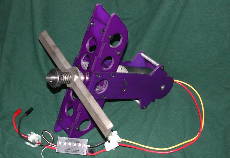 |
The completed weapon module with one of the blades. You can see the Astro 207D speed control in the lower left. Hopefully it will be enough, tests seem to indicate that it will be fine as far as current handling, and just in case we are protecting it with a fuse. |