|
|
 |
|
CDM4-PRO |
|
|
|
|
|
CDM9-PRO |
CDM12 CD-PRO |
The CDM12 CD-PRO (VAM1252) Project
|
|
|
|
CDM4-PRO |
|
|
|
|
|
CDM9-PRO |
CDM12 CD-PRO |
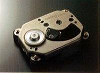
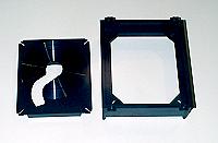
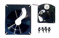
| The Philips industrial/professional grade of CD mechanism is the long time dream transport which I am looking for. The above photos show the different generations of recent Philips industrial/professional grade of CD mechanism. |
|
|
|
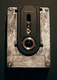
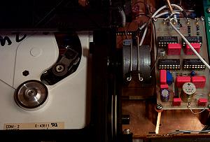
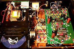
| The top side view of CD-PRO (VAM1252). The CDM12 PRO is housed with die-cast frame and enhanced sledge guidance and gearing system for 24 hrs heavy duty operation. | The bottom side view of CD-PRO (VAM1252). Four layers PCB to ensure shortest electronic routes. The CD7 decoder engine is equipped (CD-PRO 2 use CD10). |
 |
The complete kits from
Mr. Nico Thevissen,
Daisy-Laser, the Netherlands.
Recently, I am very busy and I will start this project as soon as possible. 5-26-2001 |
To be continue...
The Rebuild of "GRAMOPHONE" toy CD player
王盤的始祖 ???
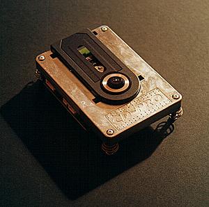
| I decided to modify/rebuild this CD
player just one week ago (12-18-2000). Occasionally, I got this
"TOY" (at least it look like a toy) for one or two years.
It was sold as a gift, so you may found it easily in a gift shop in
about ten yeas ago. Because it looks like a toy, so I just
threw it in a corner of my room. I started to pay attention to this
CD player since I found that the old CD players (eg.. Revox 226s,
Studer 740...) which equipped with Philips swing arm optic reading
unit tended to have more nature sound than what's in the market now a
day.
Sound should be easy and tensionless as well as nature and open, I supposed. In addition, I haven't a chance to listen to a CD player which equipped with CDM4 mechanism. It is the 'overture' of this story. 大約在一、二年前,在一個偶然的機會裡,我得到這一個CD唱盤。這一個CD唱盤原來是被當成禮物販賣,我還記得約十年前,在禮品店很容易看到這一個CD唱盤。因為這一個CD唱盤看起來像是玩具,所以這一個CD唱盤一直閒置在我家的某一角落,直到最近。 最近我一直有一個感覺,新的CD唱盤、DAC雖然有長足的進步,但古老時代的CD唱盤那種自然開放的聲音一直留在我的腦海,揮之不去。 因此,我決定重新對這一個CD唱盤下手。
|
| Part 1 |
GramoPhone The original |
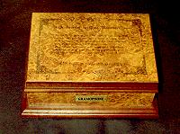 |
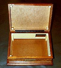
The shape of original
Gramophone was designed to simulate a jewel box antique. Box
are MDF and not well constructed, as I said, like a toy.
Gramophone原型機,仿古董珠寶盒外型,側壁及上蓋板為高壓密集板(MDF),組裝品質不太好。
|
 |
 |
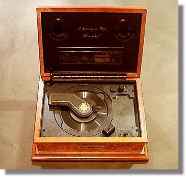
It equipped
with a philips swing arm optic reading unit. Check for the back
panel, it marked "MODEL
RPM-45 UNIT BY PHILIPS (PCDT) MKT310 CD UNIT" No
digital out found, just analog out is provided.
本機配備飛利浦搖臂式讀取係統。背板上只有類比輸出,沒有數位輸出,背板上並刻印 "MODEL RPM-45 UNIT BY PHILIPS (PCDT) MKT310 CD UNIT"。 |
|
 |
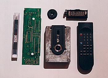
Disassembled
plastic top cover of the player and its attached control and remote
receiving unit. There is a angle plastic arm in top of the top
cover. A disk clamp is fitted in the angle arm and the all unit
looks like a old time 78 RPM LP's tone arm, hmmm.... what a cute
idea!
左圖為拆下的塑膠上蓋,此蓋連接一塊裝有搖控接收器的控制電路板。此蓋上方連接一曲型臂,CD鎮片就裝在其中,看起來有點像古老的78轉類比唱盤的唱臂。 |
|
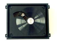   |
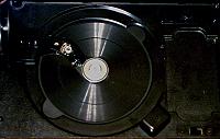
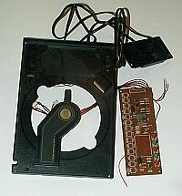
The inner
disassembled cd optic reading module. It is a CDM-4 system,
actually is model CDM-4/51. Model CDM-4/51 is a version which
equipped with a magnetic ring on the center of spin motor's top
wheel.
This is a version which can be operated by a disk clamp and is basically not for ordinary tray loading. The CDM-4 unit is mounted on a disk tray and suspended by 4 rubber grommets acted as a damper and isolator. 左圖為拆下的CD光學讀取系統,本機採用的是飛利浦CDM-4,版本為CDM-4/51,這個版本在馬達上方的承片輪中心有一個環形磁鐵,因此只要加上CD鎮片就可以操作。CDM-4固定在承片上並以4支橡膠支撐。 |
|

|
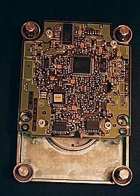
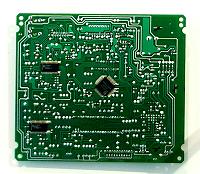
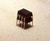
Left photo shows the MKT310 PCB, a double sided phenolic PCB. This PCB is attached at the bottom of CDM-4 unit as shows in above. This is the main and only PCB equipped with the laser reading system. It is a combo design, including the servo section, the software control section (DSA) and the dac section. All from standard Philips circuits. Laser Chip: TDA8808 Servo Chip:TDA8809 Decoder: SAA7310 DAC: TDA1543 左圖為主要的電路板,此電路板固定於CDM-4讀取系統的下方。本電路板為電木雙面電路板,其中有伺服系統、控制軟體系統(DSA)以及DAC系統。電路全是標準的飛利浦廠方公布電路,小型化而且集合化的電路。使用的晶片有: Laser Chip: TDA8808 Servo Chip:TDA8809 Decoder: SAA7310 DAC: TDA1543 |
|
|
從高傳真217期(1994.8)蒲鴻慶先生所寫『我所瞭解的王盤』文章中的照片中,我發現38℃的王盤所使用的光學讀取系統就是本機所採用的MKT310Unit,整座塑膠承盤及橡膠支撐都是一模一樣,CD鎮也是同一個,ESTI只有把CD鎮分離出來並加上一個蓋子,把所有的塑膠部分噴上一層粗糙的漆。另外ESTI也重新設計了一個控制面板,加上數位輸出及裝入元山922機箱就成了王盤!!這是故事的第一部分。 |
| Part 2 |
First Move - Light Modification stacking two DAC chips remove active low pass filter |
| Since
this cd player was intended to sell as gift.
It was basically not for hi-fi purpose.
There are two audio out, one is a pair of 2" computer
speakers mounted on the uplift top plate (the cover plate) so it can
play alone without connecting to any equipments; the other output is a
RCA jacket analog out located in the back panel.
I didn't hope much for the sound quality in such kind of design background. All test were done through the RCA analog output by connecting to my preamp and to my large system. Well, it was largely unsatisfying: the sound was not so transparent, foggy, not so clear and its musicality was poor. However, the sound still can be classified as nature, rich and airy. That’s the base of the sound of CDM-4 I guess. Overall, for the first impression, it sounded as a pretty bad tube amp comparing with a modern solid amp. 因為本機原來就是一個禮物式的商品,因此本機有兩組輸出,一組連接至上掀蓋的兩個兩吋電腦用小型紙喇叭,此小型紙喇叭可以單獨發聲,好像是古早的留聲機;另一組為位於背板的RCA接頭的類比輸出。 因上述的背景,我對本機的聲音不抱太大的期望。所有的測試都由位於背板的RCA接頭的類比輸出至前級並連至我的大系統試聽。本機原來的聲音是令我失望的:有霧、細節交代不是非常清楚且音樂性也沒讓我滿意。但是有自然、濃郁以及空氣感的聲底,難道這就是CDM-4的聲底?初次的感覺就好像聽慣了晶體機的人聽到製造不良的真空管機一般。 |
| Now,
it is about time to begin some modifications.
I decided to start to go for tuning from the basis of not making any
change for the original box, eq. a light modification.
If the change of modification of this stage is dramatic then this
player will be deserved for large modification, or just say, to rebuild.
The original power supply was quite weak aligned. It was a one stage only, 7805 and 7905 regulator with a small EI type 9-0-9 volts transformer for all laser/servo/decoder/spin moter/dac sections. Due to the space available, I couldn’t do more on the power supply. I just replaced some capacitors which I though is sonic related to low ESR type capacitors. They are about some of dc filtering, coupling, decoupling and bypassing caps. I prefer ROE EKR type’s capacitors. I also replaced the bridging diodes, OPIC of controlling spin motor from JRC4560 to AD827… For the analog section, I had to trace back from the PCB to get the original circuit. It looks like: |
|
|
| The circuit
was as simple as it could be. The TDA1543 (DAC) accepts the I2S digital signals from
SAA7310 then output analog signals followed by active low pass filter
(JRC4560) then go to a attached board then amplify to normal analog
output. Although the circuit is simple but there are many sonic
devils in it. There are too many electrolytic capacitors in signal
path (coupling). Electrolytic
capacitors as coupling capacitor tend to result in foggy sound. The
last stage, the simple and unbalanced transistor based amplification is
another sonic devil.
The following was the first trial of modifications: |
|
|
|
Foggy sound has been solved after the first modification. The sonic characteristics still keep its rich and airy basis…good. However, the gain is a little bit too small since I removed the transistor amplification stage. The most unsatisfied performance is that sound still lack of good high definition. This will result in the transparence to be not good enough.
The TDA1543 feeding by I2S digital signals remind me an article in MJ 1997 by Ryohei Kusunoki about the over sampling and digital filters. So, I decided to stack two TDA1543 DAC (picture above) and modify the active low pass filter to active buffer. The final modification became: |
|
|
| Wow, you should listen to this…Devils were vanished. Now, angels are singing. |
To be continue...
![]()
The Rebuild of Magnavox(Philips) CDB473
|
Many audiophiles still like the older Philips CD player. Especially those with a swing arm optic CD reading unit like CDM1, CDM2, CDM4 and CDM9. They claim that these CD player has thicker and more nature sound than modern CD player (linear tracking ones). Some said that it is because of SAA7220 chip and some said of swing arm... I don't want to argue with these topics. I just happened to have an old Magnavox CDB473 and it equipped with CDM2 optic mechanism. So... |
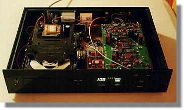 |
I found that the original plastic case
is light and weak. I heavily rebuild the case by a new design 4mm
thick black acrylic, added a 2.4 mm pure copper plate beneath the CDM2
and original board.
In the digital input of SAA7220 I put a pulse transformer to replace the original 0.1u capacitor for better isolation. I also added a PLL in the digital output of SAA7220. |
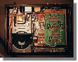
| The original power supply for the
digital and analog section is mixed and this is not good for sonic
behavior. I separated them, put a better regulation (LM317)
for each digital and analog section and add an additional R-core
transformer for analog section.
I replaced all small value capacitors in the servo section to WIMA mkp type film capacitors for a steady and reliable reading in expectation. |
 |
 |
The player equipped with Philips CDM-2 optic drive unit. CDM-2 is basically a plastic (light weighted) version of famous CDM-1 mk-II drive unit. They have same servo circuit. I added a PLL board to improve the quality of digital output. |
 |
The green add on board is a 24bit PCM1702 + AD1853 dac from Mr. Tolonen Jukka, Finland. You can visit his web site for detail. A nice guy and useful info on his web. |
The Rebuild of Luxman PD274 LP Turntable
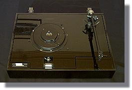
| The original Lux PD274 is a
direct drive turntable with wooden (MDF) case. It equipped with a
tonearm developed by Lux themselves.
This a not a high grade LP turntable but it went along with me more than 10 years. Ten years of usage induced a serious weathering problem. I decide to rebuild this old LP turntable. |
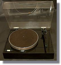 |
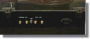
The completed rebuilt Lux
PD274 is shown left including the original dust cover.
Below shows the back panel of this turntable. There are two sets of output, one is from tonearm directly and the other one power by built in RIAA phono pre.. |
|
|
 |
The main materials used in case
structure is 10mm
thick black acrylic plates.
There are totally 3 layers in the case. Between the top and middle layer of acrylic plates, 4 springs are fixed to suspend the main alumni turntable and the tonearm, so the turntable and the tonearm is fixed at the same top layer and free of shock and vibration. I updated the original tonearm to a famous Rega RB-300 tonearm. |
 |
The main turntable is
directly driven by a Seiko brushless motor. I depart it and
remounted to the top layer. Since the top layer is isolated to the
edge/sides panel so 3 anti-drop screw is placed in hollow holes as
shown in the left.
The location of the 4 suspension springs are carefully calculated to be consist with the center of gravity of the whole turntable. |
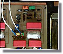
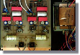
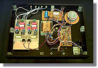
| Between the middle and the bottom
layer, all electric components are placed. The 8 clear black
acrylic columns are designed to be a spacer and a stiffener like
honey-bee house/nest as shown in the right.
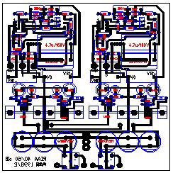
The left PCB is the RIAA phono stage. |
 |
|
The role of this RIAA circuit is linear technology LT 1010, LT1115 OP-IC. PCB lay out by autocad as shown above. I will transform it to pdf file if needed. |
|
|
|
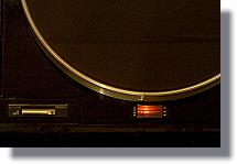 |
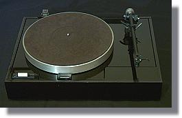
The turntable in action. Note for the small red window located in the bottom of the picture, which is the speed indicator. This turntable is not quartz PLL circuit controlled. |
Under Construction !
|
|
|