 |
 |
The information in this document is provided "as-is". I assume no responsibility for any damage taken on hardware or personal health.
The ADNS 2030 chip from Agilent is the standard chip used in most optical mice these days. Besides this apparent functionality, however, it is possible to read the image buffer from this chip, which uses a small CMOS image sensor (16x16 pixels). While this won't be enough for building your own web camera, it might be nice for some experiments.
I will describe shortly how I built such a "mini-camera" and connected it to an 89S8252 microcontroller from Atmel. I used this 8051-derivate on an experimentation board (89S8252 Flash Microcontroller Board, see pictures below) which was introduced by Elektor, an electronics magazine available in Germany, The Netherlands, France and in the UK.
For detailed information on the ADNS 2030, check the datasheets, available from Agilent (see link above). For detailed information on the 89S8252 Flash Microcontroller Board, see the Elektor website.
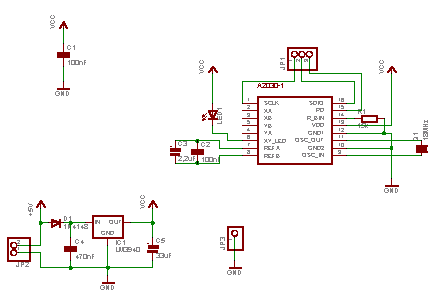
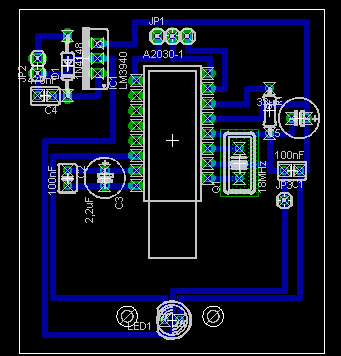
The Microcontroller Board provides 5V DC. Since the ADNS 2030 is powered at 3.3V, a LM3940-3.3 was used to regulate the voltage from the Microcontroller Board. There are just a few peripheral components to use the ADNS 2030, so both the schematic and the PCB were easily done. For doing this, I used the (free) Lite Version of Eagle, available at http://www.cadsoft.com.While the schematic was straight-forward, the PCB was not, since the ADNS 2030 has a somewhat peculiar footprint (see below). But it is quite easy to define your own parts in Eagle-CAD. The library is included in the ZIP, together with the schematic and board file.
|
|
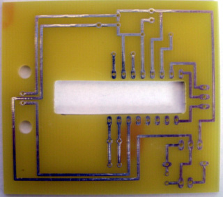
Another speciality is the fact, that the aperture of the image sensor is on the bottom of the chip, hence you have to saw a chasm into your PCB (I simply used a jigsaw):
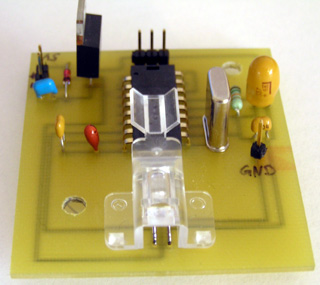
The ADNS 2030 datasheet gives a good description how the PCB should be designed and how the whole thing should be assembled. I ordered the sample kit ADNK-2030, described on the Agilent homepage, from Farnell, which includes 5x ADNS 2030 and accompanying sets of lenses and LED's. The assembled PCB looks like this:
 |
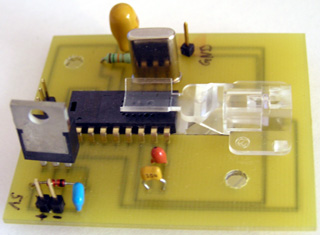 |
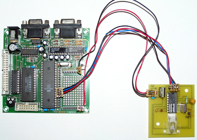
The plastic clip holds the LED and reflects the light from it in the right angle. A second lens on the bottom (not visible on the pictures) catches this light and directs it to the ground, where the ADNS 2030 senses the reflection. The GND pinhead is used for debugging, the two 5V pinheads are the power source and the three pinheads on top of the ADNS 2030 is the interface to the 89S8252. The ADNS 2030 uses a simple serial protocol to transmit and receive commands or data, just check the datasheet. To implement that on the 89S8252, I used the C-Compiler ReadS 51 from Rigel, which has a nice IDE and is free for non-commercial purposes. Find the code for reading the ADNS 2030 in this ZIP. The code is well commented and shouldn't be too hard to understand. I use the RS232 interface (@ 9600,N,1) on the Microcontroller Board to transmit the image data to a PC, etc. The transmission is started as soon as a '$' character is received on the RS232, and a 'z' is appended at the end of the image data to signal end of transmission. While this is certainly not fool-proof, it serves testing purposes well. Since the image data is 6-bit (i.e. the value range is from 0 to 63), the character 'z' (= 122) won't be mixed up with image data.
The whole setup looks like this:
I then created a little test app in MS Visual C++ 6.0, using MFC, to read and display the image from the ADNS2030. Find the code in this ZIP. Please note that all the code and schematics/PCB wasn't designed with optimization in mind. It was all just some experimenting and testing. The images from the ADNS2030 look quite awkward, since they're in extremely small resolution. I won't include examples here, just check those given in the datasheet. However, with a bit of fiddling, one might find a useful application. I thought of a 2D barcode scanner or something like that. One might employ a different lens, though. With the one provided in the Sample Kit, even a 2.54mm (0.1 inch) thick line fills out the entire image!
In the schematic/PCB I did not connect the Quadrature pins, and did not consider them in the code, too. So if you just want to build your own optical mouse, you would have to redesign the whole thing. But with the help of the datasheet and my paradigms it won't be hard.
© 2004/2005 Alexander von Lünen, Last Modified: 28/06/05