|
Operation |
VTEC
OPERATION SYSTEM
What does the
VTEC system in a Honda engine do?
There is a book entitled How Car Engines Work, telling about the
valves that let air into the engine and let exhaust out of the engine. It also
tell about the cam shaft that controls the valves. The camshaft uses
rotating lobes that push against the valves to open and close them. This is an
animation from How Car Engines Work to help understand how
the cam shaft opens and closes the valves:
It turns out that
there is big relationship between the way the lobes are ground on the camshaft
and the way the engine performs in different RPM ranges. To understand why this
is the case, imagine that we were running an engine extremely slowly - at just
10 or 20 RPMs, so it took the piston seconds to complete a cycle. It would be
impossible to actually run a normal engine this slowly, but imagine that we
could. We would want to grind the cam shaft so that, just as the piston starts
moving downward in the intake stroke, the intake valve would open. The intake
valve would close right as the piston bottoms out. Then the exhaust valve would
open right as the piston bottoms out at the end of the combustion stroke and
would close as the piston completes the exhaust stroke. That would work great
for the engine as long as it ran at this very slow speed.
When you increase
the RPMs, however, this configuration for the camshaft does not work well. If
the engine is running at 4,000 RPM, the valves are opening and closing 2,000
times every minute, or 3 to 4 times every second. When the intake valve opens
right at the top of the intake stroke, it turns out that the piston has a lot of
trouble getting the air moving into the cylinder in the short time available (a
fraction of a second). Therefore, at higher RPMs you want the intake valve to
open prior to the intake stroke - actually back in the exhaust stroke - so that
by the time the piston starts moving downward in the intake stroke the valve is
open and air moves freely into the cylinder during the entire intake stroke.
This is something of a simplification, but you get the idea. For maximum engine
performance at low engine speeds the valves need to open and close differently
than they do at higher engine speeds. If you put in a good low-speed camshaft it
hurts the engine's performance at high speeds, and if you put in a good
high-speed camshart it hurts the engine's performance at low speeds (and in
extreme cases can make it very hard to start the engine!).
VTEC (which stands
for Variable Valve Timing and Lift Electronic Control) is an electronic and
mechanical system in some Honda engines that allows the engine to effectively
have multiple camshafts. As the engine moves into different RPM ranges, the
engine's computer can activate alternate lobes on the camshaft and
Several engine
manufacturers are experimenting with systems that would allow infinite
variability in valve timing. For example, imagine that each valve had a solenoid
on it that could open and close the valve under computer control rather than
relying on a camshaft. With this type of system you would get maximum engine
performance at every RPM. Something to look forward to in the future.
Variable Timing Control (VTC) Operating Principle
How
does VTC effect VTEC system
Honda's VTC
operating principle is basically that of the generic variable valve timing
implementation (this generic implementation is also used by by Toyota in their
VVT-i and BMW in their VANOS/double-VANOS system). The generic variable valve
timing implementation makes use of a mechanism attached between the cam sprocket
and the camshaft. This mechanism has a helical gear link to the sprocket and can
be moved relative the sprocket via hydraulic means. When moved, the helical
gearing effectively rotates the gear in relation to the sprocket and thus the
camshaft as well.
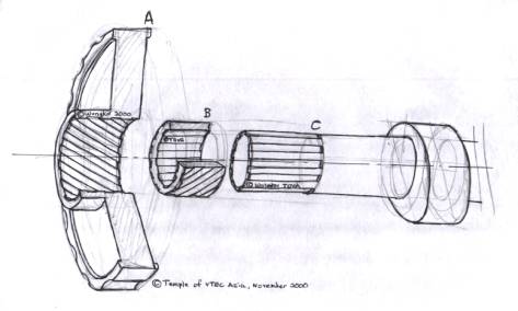
 The
drawing above serves to illustrate the basic operating principle of VTC (and
generic variable valve timing). A labels the cam sprocket (or cam
gear) which the timing belt drives. Normally the camshaft is bolted directly to
the sprocket. However in VTC, an intermediate gear is used to connect the
sprocket to the camshaft. This gear, labelled B has helical gears
on its outside. As shown in the drawing, this gear links to the main sprocket
which has matching helical gears on the inside. The camshaft, labelled C
attaches to the intermediate gear.
The
drawing above serves to illustrate the basic operating principle of VTC (and
generic variable valve timing). A labels the cam sprocket (or cam
gear) which the timing belt drives. Normally the camshaft is bolted directly to
the sprocket. However in VTC, an intermediate gear is used to connect the
sprocket to the camshaft. This gear, labelled B has helical gears
on its outside. As shown in the drawing, this gear links to the main sprocket
which has matching helical gears on the inside. The camshaft, labelled C
attaches to the intermediate gear.
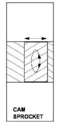
The supplementary
diagram on the right shows what happens when we move the intermediate gear along
its holder in the cam sprocket. Because of the interlinking helical gears, the
intermediate gear will rotate along its axis if moved. Now, since the camshaft
is attached to this gear, the camshaft will rotate on its axis too. What we have
acheived now is that we have move the relative alignment between the camshaft
and the driving cam-sprocket - we have changed the cam timing !
VTC and other
implementations of generic variable valve timing can only change the relative
alignment between the camshaft and its driving sprocket. What this effectively
does is to change the relative timing between the intake and exhaust cams
and thus their valve opening cycles or the intake and exhaust valve opening
overlaps. Note that no other valve timing parameters, eg amount of valve lift or
absolute valve opening duration can be varied. The only thing that VTC varies is
the valve opening overlaps. VTEC is able to vary all valve timing parameters but
current implementations does so in two or three distinct stages (or profiles).
Adding VTC allows the valve opening overlaps to be continously varied and thus
enables the power delivery from the standard VTEC system to be further
fine-tuned. The greatest impact will be to the mid-band power delivery of the
engine. Most importantly, VTC (and generic valve timing systems) will not
replace VTEC but enhance its effectiveness.
|
Operation |