Digital RPM
I started this project for two main reasons :
1- because my car has no RPM and clock
2- to learn and jump into the amazing world of Microcontrollers

My project divided into two main parts :
Part one : designing the circuit and test it at home
Part two : to install the circuit in my car�s dashboard
Part one : designing the circuit and test it at home
Parts List
Microcontroller PIC16f628a  (for this project 16f84a does work also with minor changes)
HD44780-based Character-LCD 16 *2
7805 Regulator
Led
�.
�.
�.
�.
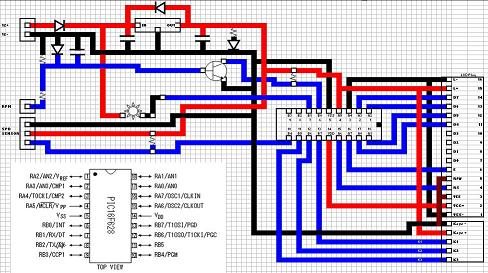
And below is the final diagram
And here is some pictures of the Alfa Version of the circuit
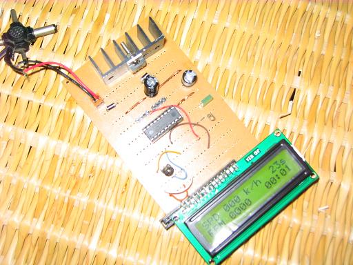
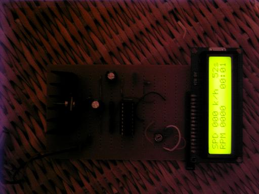
And finally became

Circuit theory :
 The circuit is a general counter circuit which receive the signals from the engine ignition coil (based on the ignition Type) and count it every .5 second  ,then send the result to the LCD in 3 formats :graphical, RPM  and the max RPM /Min.
For the clock (which is required also to count the RPM pulses) , it is based on the Roman Black algorithm.
Future Plane : is to add the Temp & Speed
Part two : to install the circuit in my car�s dashboard
If you plane to make a similar circuit ,you have to gather some information about your car , ignition type , electric wires �.etc
Ignition types (Multi cylinder engines):
Distributor ignition :

To read RPM in this schema, you only need to place the capacitive clamp on the main HV cable (from coil to distributor). This will pick all RPM pulses (2 sparks per rev)
TCI ignition (wasted spark):

Two cylinders are fired at the same time. One of them is in compression phase, and it fires the air-fuel mixture when spark is made. The other cylinder is in exhaust phase, and spark has no effect over it.
To read RPM in this schema, you only need to place the capacitive clamp on any of the outter HV (1 or 4) taking care that the sensing cable doesn't touch the other HV cables to prevent to catch pulses from the other coil.
This will pick RPM pulses from one coil (1 spark per rev)
On-spark coils :

In this schema each spark has its own coil, and there is no HV cable from the coil to the spark. This schema can be used both for TCI and CDI ignitions. The ECU can fire each spark one by one.
To read RPM the difficulty with the current capacitive method is that the HV pulse is made inside the coil and there is no HV cable, so it is difficult to catch the ignition pulses with the capacitive clamp.
A thick wire can be placed inside the coil going outside it, so the capacitive clamp can be placed over it.
ODD ignition (V- engines)

The two cylinders are fired at the same time (equal as wasted spark), but the firing time is not always the same because the cylinders are in V configuration.
When Cylinder 1 is compressing the mixture, cylinder 2 is starting exhaust phase, so spark in cylinder 2 has no effect. And when cylinder 2 is compressing, cylinder 1 is ending exhaust phase, but no new air-fuel mixture has started to enter, so spark in this moment has not effect.
When read timings it seems to be not steady. For example at 3000 rpm (20 ms), timing will be: 25 ms, 15 ms, 25 ms, 15 ms, and so on...
You can overcome this problem in the SP1 and SP3 by group always two samples:
(25 + 15)/2 = 40 / 2 = 20 ms -> 3000 rpm
and if sequence is taken backwards it works too:
(15 + 25)/2 = 40 / 2 = 20 ms -> 3000 rpm
Back to my car........
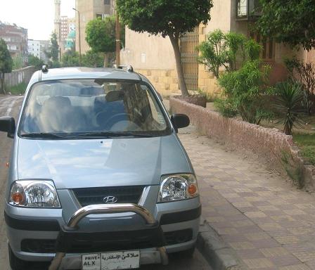
....my car is Hyundai Atos 2006 ,and it is based on a TCI ignition (wasted spark),so the source of the RPM Signal will be as below :
-cnnct-circuit-640x620p.jpg)
now�lets go to work ��.
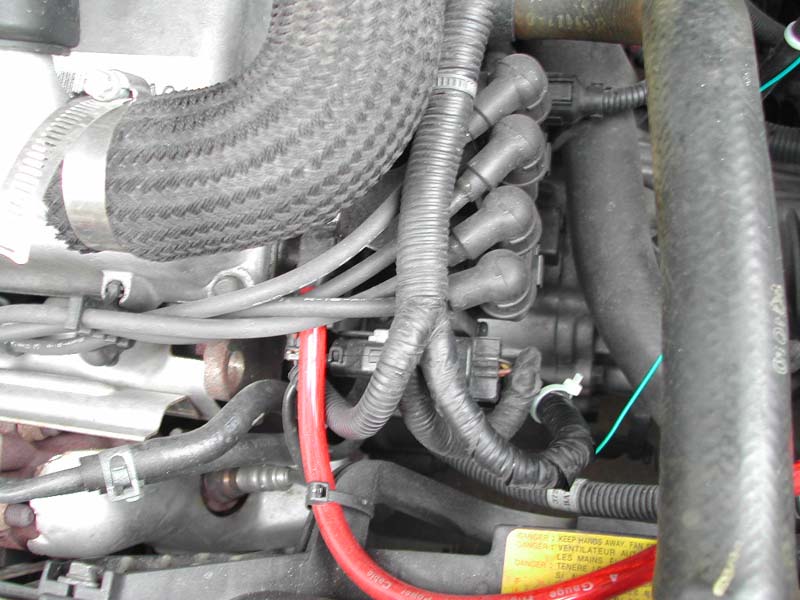
first we have to figure out the place of the coil :
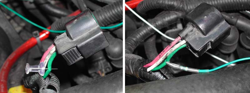
then unplug the cable and attach the signal wire:
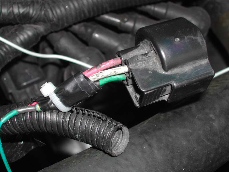
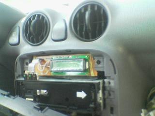
and after finishing the engine room work now the dashboard part�..
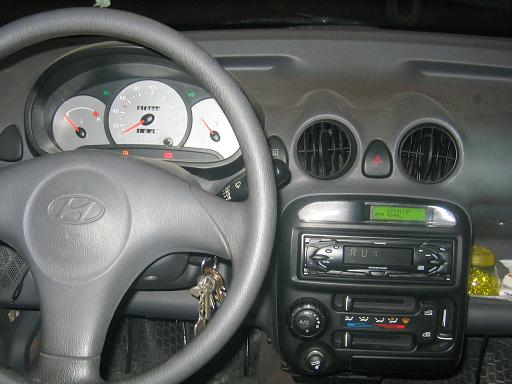
Hyundai Atos has a nice dashboard with three Extra Keys that Useless for me :
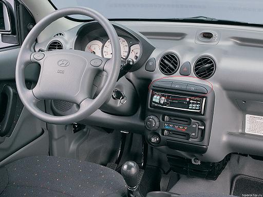
(It is not mine but it is similar as I forgot to catch a before picture)
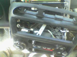
Remove the black panel which carry all the keys :
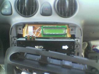
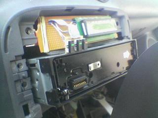
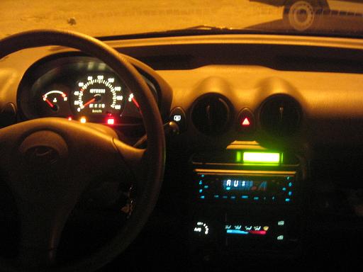
Test :
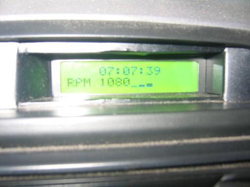
Night view :