- Am Detector Upgrade
This will increase the signal of distant stations from 3 to 6 DB and reduce
the noise floor. A receiver alignment is not necessary, but could be done to
ensure proper alignment.
Change D34 & D35 to NTE583 Schottky Diodes.
Change Q18 to a 2SC2999 (Keep for SSB Upgrade) - SSB Detector Upgrade
Change Q16 to 2SC1674 (Taken from Q18 AM Detector) - NB Upgrade
This will make your Noise Blanker more effective.
Change D1 & D2 to NTE583 Schottky Diodes. - Audio Modification
Change R178 to 3.3k ohm
Change R194 to 3.3k ohm
Change R170 to 3.3k ohm
Parallel C270 with a 470pf 1kv disc cap. - Swing Mod
This will give you max peak power at any position of the RF Power knob.
Lift the opposite end of R281 that feeds to VR13 and solder a 1N4148 Diode
in series. Make sure the banded end goes toward the junction of R282 and
C299. - More Power Mod
add 330pf caps across C261 & 262, then retune for best output. - TX Stability Modification
Will help produce a more clear transmission on AM and SSB without any
warble.
Change Q53 2SA1869 or 2SA473 to 2SA1012
Change Q51 2SB754 to 2SB817 - Frequency Modification
Remove the bottom cover. There will be a small PC board immediately behind the front panel.
Locate "J2". There will be a jumper on pins P3 and P4.
Remove this jumper to expand coverage to 26 MHz - 29.7 MHz.
Move the jumper from P3-P4 to P1-P2 to expand coverage to 26 MHz - 32 MHz.
After moving (or removing) the jumper, press the CPU reset button (located below J2).
NOTE: Operation between 30-32MHz may require retuning the VCO. - CB Channel Readout Modification
Locate J1. There will be a jumper on pins P1-P2.
Remove jumper and place on P2-P3.
Press the LOCK button on the front panel. The readout will now
display the CB channel number 1-40 -- also will display "A" channels.
Press LOCK again to see the frequency of the channel you are on.
Press the MAN button to return to the VFO Mode
NOTE: The SHF button will not operate while in CB mode. This modification will disable the frequency lock function. - CB Channel 9 Select Modification
Locate J3. There is a jumper between P1-P2.
Remove the jumper and place it on P2-P3.
Press the "roger beep" button to go directly to CB Channel 9.
NOTE: Doing this modification makes it impossible to turn off the roger beep feature (unless, *possibly* you make sure the roger beep is turned off before moving the jumper. I'm not sure). - Tuneup Modifications
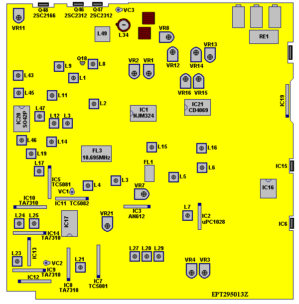
Adjust VR14 (AMC) for maximum forward modification. Mod limiter Q32 can be removed for more modulation, but it also disables VR12 (SSB ALC) and disables variable power for SSB. I do not recommend removing Q32; you'll have plenty of modulation as is.
Tune L34, L13, L14, L46 and L10 in AM mode for maximum forward swing, using a peak-reading wattmeter. Try to balance for even power from top to bottom of frequency range. NOTE: You'll have a LOT of trouble identifying these cans. Sorry, I don't know for sure where they are either.
Adjust VR13 (AM High Power) for 12 watts dead key with the front panel RF power control at maximum. Adjust VR15 (AM Low Power) for 2 watts dead key with front panel RF power control at minimum. From the 12-watt dead key you should see a forward swing of 30-40 watts. From the 2-watt dead key you should see a forward swing of 18-20 watts.
Adjust VR12 (SSB High Power ALC) for maximum PEP on SSB, then back off just a little, with front panel RF power control at maximum. Adjust VR16 (SSB Low Power ALC) for 5-6 watts PEP on SSB with front panel RF power control at minimum. You should see 40-50 watts PEP on SSB with front panel RF power control at maximum.
- Microphone wiring diagram
Pin 1 -- shield
Pin 2 -- Audio
Pin 3 -- Transmit
Pin 4 -- Receive
Pin 5 -- Frequency select up \ These might be reversed.
Pin 6 -- Frequency select down / - Clarifier Mod
Locate R-197
Unsolder the wire lead side of R197 that goes to the black wire of plug
Make sure that the "hole" is cleaned out good from where R197 was removed
Solder a piece of wire from this hole to Pin #3 of IC6 (about 6 inches)
Remove D-59 & the rest of R197
L27 = AM
L28 = LSB/CW
L29 = USB - Switchable or Full time talkback
Install a SPST Switch between one of the leads to D78 for switchable or remove D78
completely for full time talkback. Replace D115 with a .0047 uf ceramic cap. - Receiver Temporarily Shuts Down
This is an AGC overload. Locate R49 and replace with a 470K resistor. I have not tested this one yet. It also contradicts the mod directly below. - Close-Range Receive Improvement
Change R49 (near IC 1) from 100k to 33k. This will keep very close signals from overdriving the front end of the radio. - Very "Noisy" Receiver
Locate R78, a 2.2 K resistor and replace it with a 6.8 K resistor.
NOTE: This will slightly degrade the receiver and make the RF Gain more touchy.
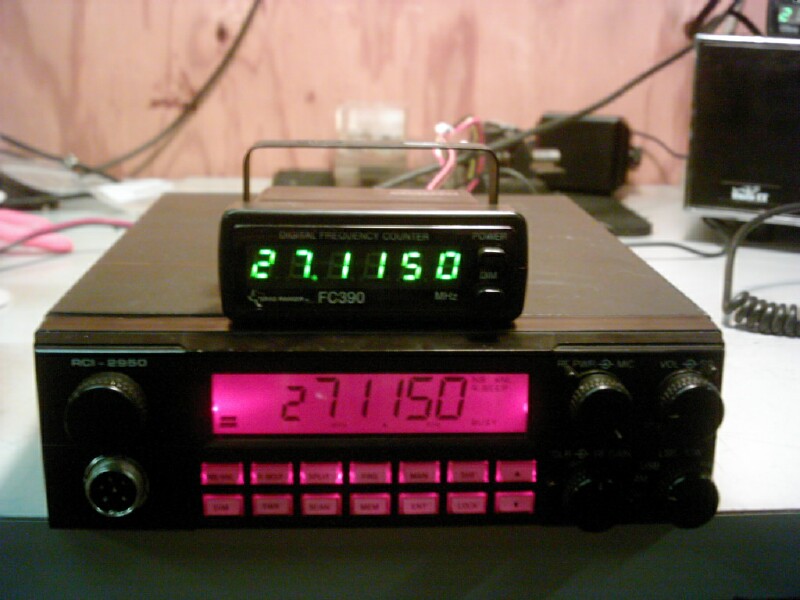
Hooking a Texas Ranger FC-390 or Galaxy FC-347 Frequency Counter to an RCI-2950 or RCI-2970 Below is how to hook a Texas Ranger FC-390 or Galaxy FC-347 to an RCI-2950 or RCI-2970. Just hook the cable up like below. NOTE: You will most likely need to realign the radio after you install.
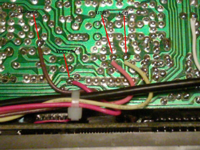
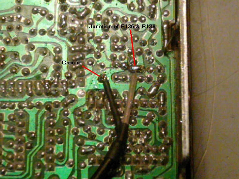
In most cases, a slight adjustment to VC2 (right next to X2) would bring the radio synthesizer on frequency. Transmitter alignment would need to be AM=L27, LSB/CW=L28 and USB=L29...