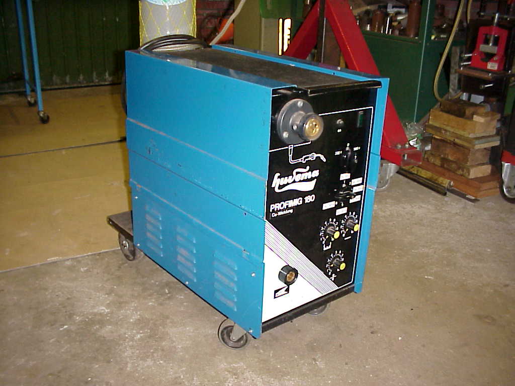
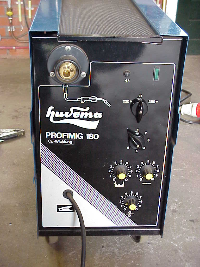
A typical example of a MIG/MAG welder can be seen in figure 11, where the gasbottle, necessary for this type of welding and mostly placed on the backside of the welding machine, is hardly visible. In this picture, the torch and the earthing cable are disconnected.
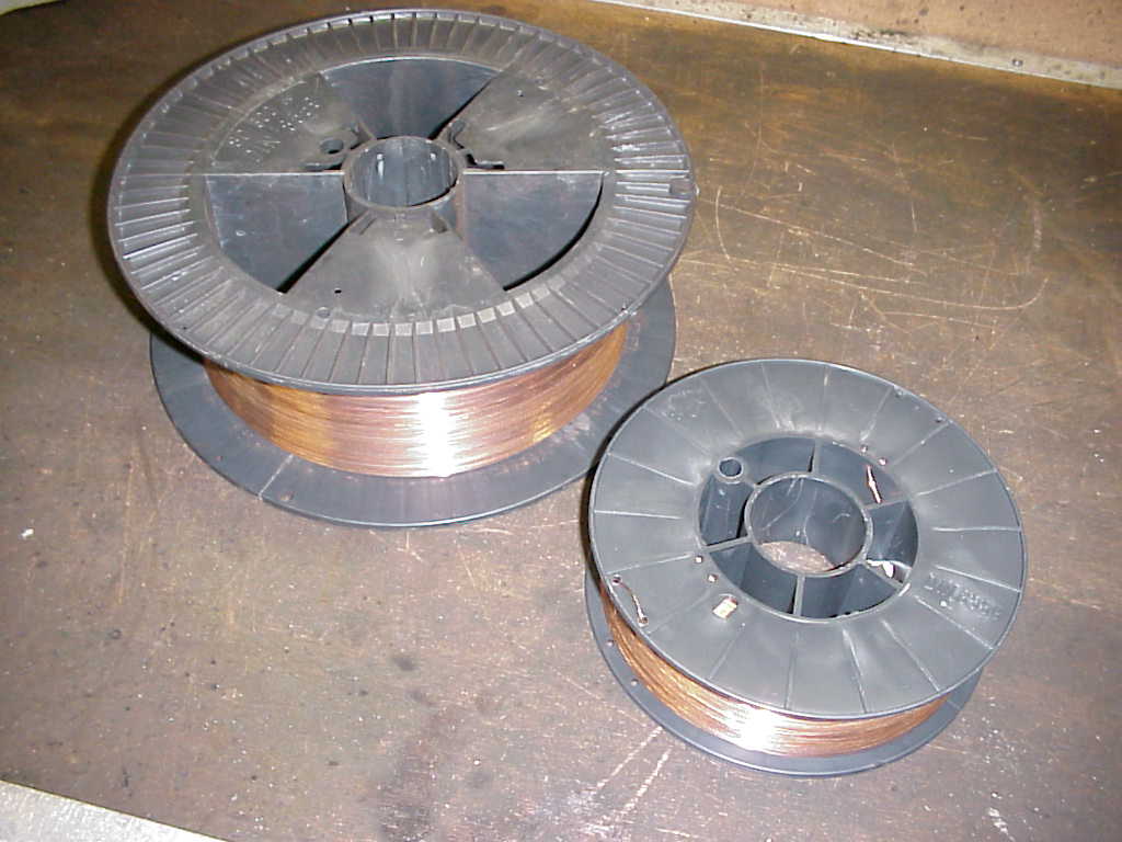
Besides the welding machine containing the welding transformer and the rectifier, a MIG/MAG welder further consists of a gasbottle with pressure reducer, a welding torch and an earthing cable with earthing clamp. The energy necessary for MIG/MAG welding is, identical to metal arc welding, generated by an electrical arc between the workpiece and the melting-off elektrode (the filler wire). This elektrode can either be a solid wire or a filled wire (fluxed core wire) spooled on a reel that is placed in or on the welder, see figure 12. These reels are available in several sizes, depending on the type of welder. The left hand side of figure 12 shows a 15 kilogram filler wire reel, whilst the right hand side of figure 12 shows a 5 kg filler wire reel. It is important to protect the reels against moisture, because moisture will cause corrosion (rust) which has a detrimental influence on the welding process.
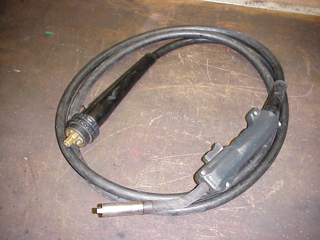
Filler wire is available in several diameters, ranging from 0,6 mm to appr. 2,0 mm. For welding of thin sheet metal, a wire diameter of 0,6 mm or 0,8 mm is most suitable. The welding process is started by pressing the starting button on the welding torch, and during the welding process, the filler wire is automatically fed to the the welding puddle through welding torch. Filler wire speed can be adjusted. The welding puddle is protected from the surrounding air (oxygen) by a so called shielding gas from the gas bottle that is fed to the welding puddle with a certain pre-set flow. Figure 13 shows a typical example of a welding torch with the handle on one side of the welding cable and a screwed connection to the welding machine on the other side of the welding cable. The screwed connectors are available in several sizes depending on the power rating of the welding machine. The filler wire is guided through the torch by a spiral liner. For welding Aluminium, this liner should be made of Teflon to prevent the relatively soft aluminium filler wire from tucking-up and thus clogging the liner.
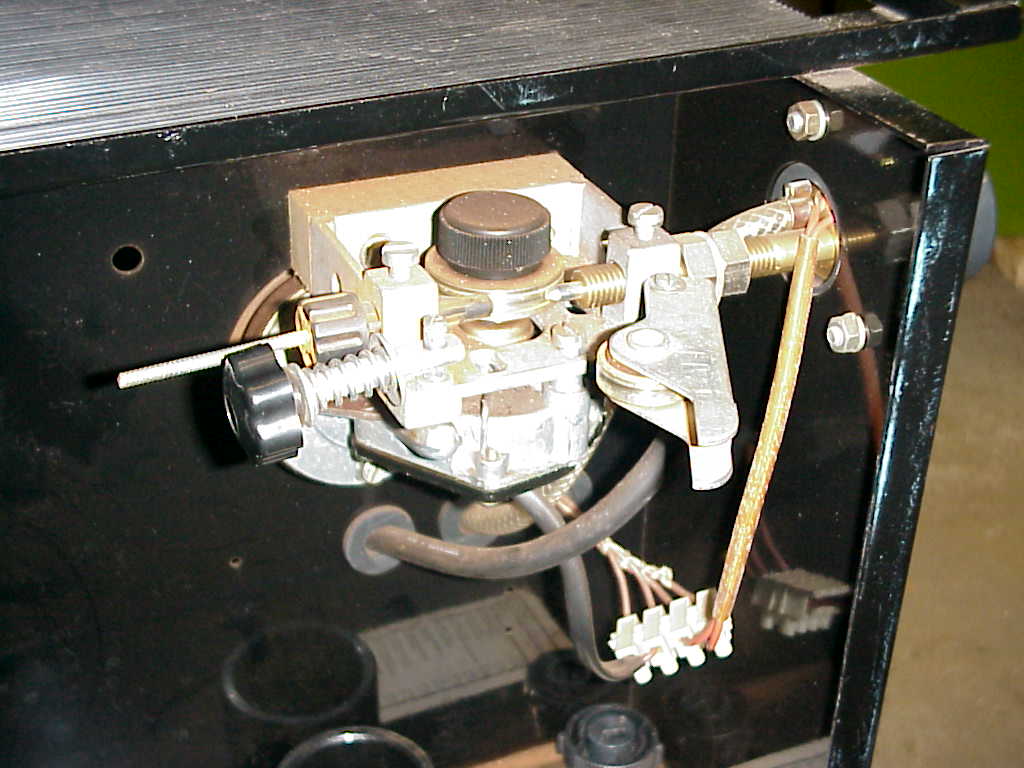
The filler wire is fed through the liner by the transport mechanism inside the welding machine as shown in figure 14.
The basis of this wire transport mechanism consists of two steel wheels (rolls) of which one is electric motor driven. The steel rolls are grooved and the filler wire runs over these grooves. The wire tension is adjusted by an adjusting knob. The speed of the driven roll can be adjusted and controls the feeding rate of filler wire during welding.
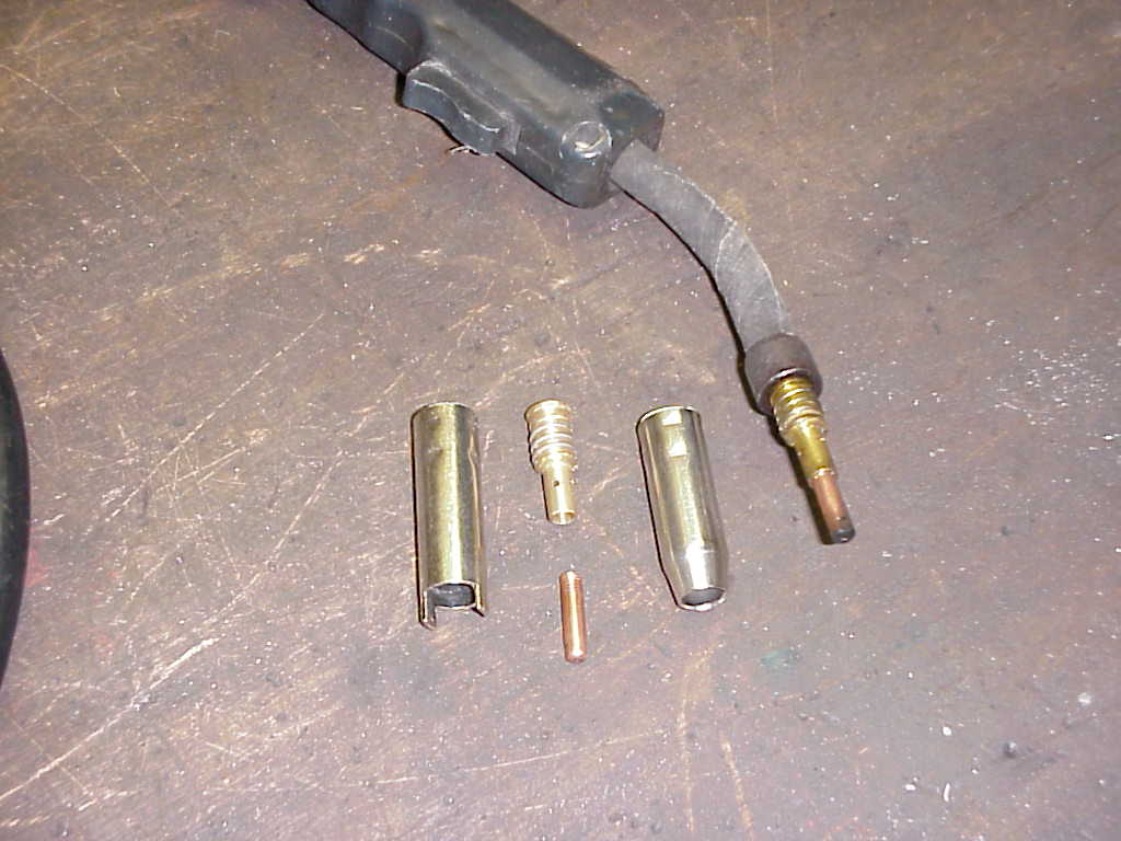
The welding torch further consists of a gas nozzle, a contact tip and a gas diffuser with nozzle spring, see figure 15.
Figure 15 shows two types of gas nozzles. The left one is also called a spotwelding nozzle, and is used for making spotwelds or tackwelds, which is commonly used when restoring thin autobody sheeting. The nozzle edge is positioned on the metal surface and enables exact aiming at the welding spot, and still having a clear view on the welding puddle and surrounding area.
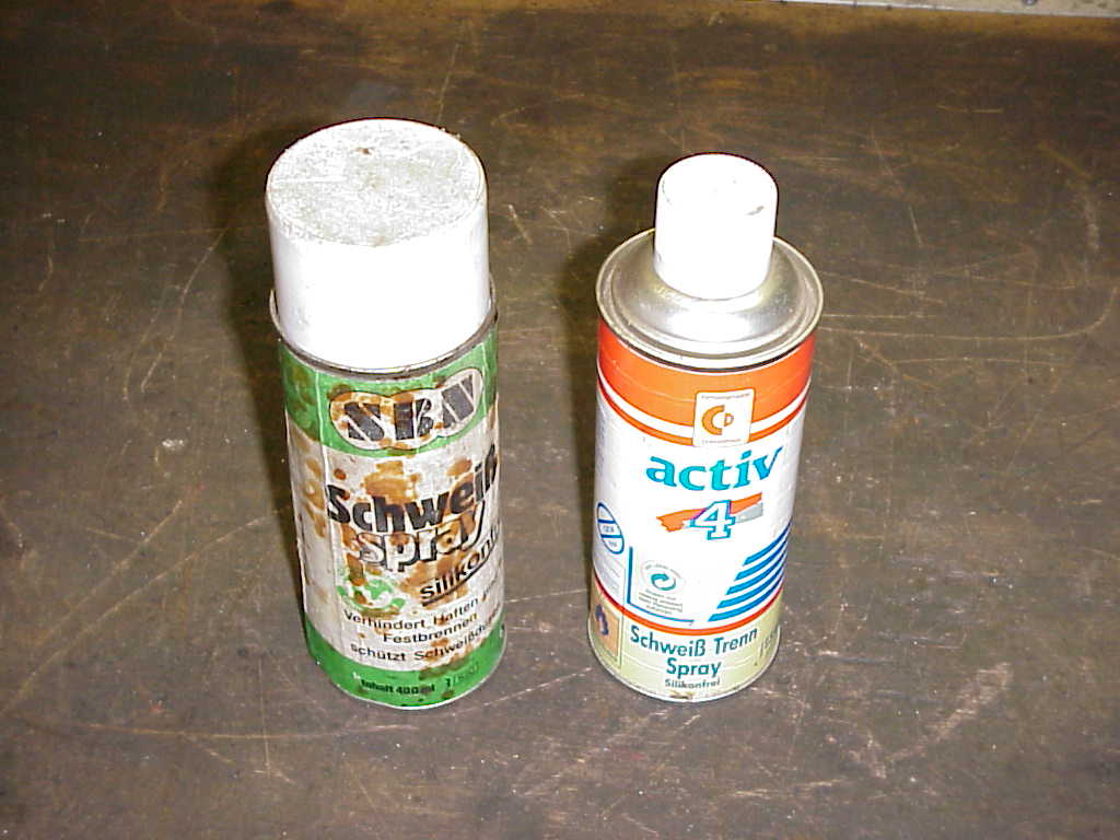
The copper contact tip, through which the wire is running, provides a good electical contact between the filler wire and the welding machine, and every diameter filler wire has its own contact tip diameter. Although the above mentioned parts are not considered consumables as such (like filler wire), it is important to keep these parts clean and replace them when worn. A gas nozzle clogged with metal drops will cause a non-uniform shielding gas distribution profile around the welding puddle, and cause defective welds. To prevent molten metal drops sticking to parts of the torch, special welding sprays can be used, see figure 16. Using this spray on the mentioned torch parts will prevent metal drops from sticking, and the torch can be cleaned much easier. A special so called spray box is available for easy use of the the spray can.
The abbreviation MIG/MAG stands for Metal Inert Gas (MIG) and Metal Active Gas (MAG), and both refer to the shielding gas that is used to protect the welding puddle from oxygen from the surrounding air. Non-ferro metal welding of e.g. Aluminium is done according to the MIG-welding proces, using an inert shielding gas (mostly Argon or mixtures of Argon and Helium). Inert means that the shielding gas molecules do not take part in the reactions during the welding process.
For welding sheet metal, mixtures of Argon (Ar) and Carbondioxide (CO2) have proven to give the best welding results. A typical gas mixture contains 75 vol% Ar and 25 vol% CO2, and is known as Stargon� and Goldmix� which are trade names. We speak of MAG-welding, because the CO2 molecules in the shielding gas take part in the reactions during the welding process, which has a positive influence on the arc stability, the material transfer and the welding puddle behaviour.
The shielding gas comes in steel bottles (welding cylinders), and the shielding gas passes through a main valve and gas reducer to the welding torch.
Gas bottles are available in several sizes, and can be identified by an international color code. The old color code for Ar/CO2 gas mixtures was a gray/dark-green bottle-shoulder (upper part of the gasbottle), while the new color code is a lightgreen shoulder (RAL 6018) and a possible letter �N�, indicating the the new color code has been used. Maximum filling pressure of the Ar/CO2 cylinder is 200 bar gauge at 15 degrees C.
Apart from welding with gas shielded massive filler wire, it is also possible to weld without shielding gas using fluxed core filler wire. This type of welding is often referred to as FCAW (Fluxed Core Arc Welding) The flux components in the core of the filler wire react during the welding process to form gasses that act as a shielding gas. Main disadvantage of this type of welding is the spatter of molten steel drops that stick to the surrounding metal. These have to be removed mechanically by grinding. For this reason, FCAW is not recommended for welding thin sheet metal.
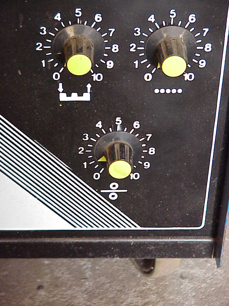
Because both filler wire and shielding gas are fed to the welding puddle �automatically�, MIG/MAG welding is also called half-automatic welding. A number of welding parameters controlling the welding process have to be adjusted on the welding machine. These parameters are gasflow, wire speed, wire tension and welding current. The welding current is controlled by a knob, just as the wire speed, see figure 17a and 17b for a typical example of a control panel of a MIG/MAG welding machine.
� Alfred Westenbroek M.Sc.