Wheel
arrangement:
2-2-2
Leading
wheels:
4’ 8” diameter
Driving
wheels:
6’ 3” diameter
Trailing
wheels:
4’ 0” diameter
Wheelbase:
8’ + 7’ = 15’ total
Length:
23’ 8” over buffers
Height
above rail –
chimney cap:
12’ 8”
boiler centre line:
6’ 6”
Boiler
–
length:
11’ 11” between tubeplates
tubes:
151 of 2 and 1/8”
external diameter
tube heating surface:
1000 square feet
firebox heating surface:
60
square feet
total heating surface:
1060 square feet
working pressure:
80 lbs per square inch
firebox grate area:
12·75 square feet
Cylinders
(2, inside):
15” diameter x 20” stroke
Weight:
22 tons 19 cwt
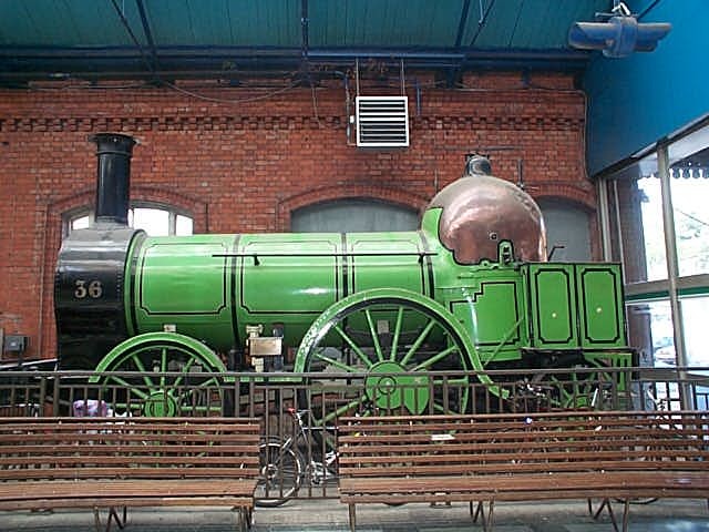
The
frame is a typical Bury forged iron bar-frame with rectangular-section top
members and round-section bottom trusses.
The
firebox is the typical round pattern with a grate which is D-shaped in plan and
with a ‘haystack’ domed top with sheet copper cladding; the internal firebox
is made of copper with crown bar-stays. The
brass dome on top of the firebox carries two Salter spring-balance safety valves
with levers pointing fore and aft; there are three water-level test cocks on the
left side of the firebox, and a water gauge (glass tube and cocks are missing)
on the right side. Near the top of
the firebox on the left side is a warming cock (the delivery pipe, for taking
steam down to the tender water feed pipe, is missing); the regulator handle
(throttle) is centred above the firehole; the diagonal rod behind the driving
wheel, with its handle low down on the left side of the footplate, controls the
ashpan damper; the large lever in a notched quadrant-plate at the right side of
the footplate is the reversing lever. This
lever alters the steam valves via the expansion links of the valve gear to allow
more economical running, and for reversing the engine. There is no protection, not even a weatherboard, for the
driver and fireman on the open footplate.
The
valve gear is Stephenson’s Link Motion with expansion links centrally
suspended from a weighshaft mounted above the frame; the weighshaft carries a
balance weight at each end, on short arms pointing forward, just behind the
smokebox. Horizontal valves above the cylinders are operated by
valve-rods driven by rocking shafts; the lower arm of each rocking shaft engages
directly with the pin of the die-block in the link.
The rocking shaft trunnions are fastened to the top of the slide-bars.
At
85% of working boiler pressure and with driving wheel diameter a nominal 6 feet,
the tractive effort would be 4250 lbs.
The
engine is standing on a length of the original GS&WR track of 1846:
‘bridge’ section rails weighing 90 lbs per yard, the heaviest then in use.