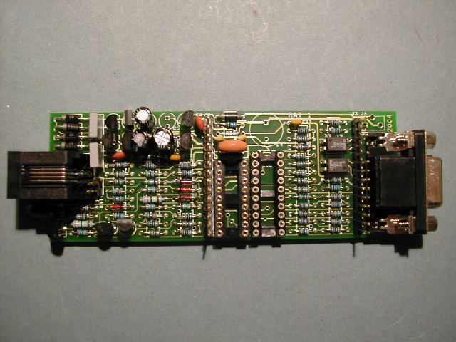
You have just finished building your RAT_1 kit...
To test it you will need a digital multimeter, a 24V bench power supply and a 1K, 2W power resistor.
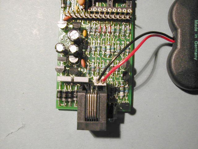
You will also need some hook-up wire or an old telephone line cord fitted with an RJ11 jack.
Make up a temporary lead to the power supply with the resistor in the positive lead and connect to the phone line connector.
Working with this safe low voltage supply, the main parts of RAT_1 can be tested by making a few simple voltage measurements.
Check the pcb carefully for dry joints, unsoldered pins and short circuits before plugging in the battery.
Also check that all the transistors are correctly fitted.
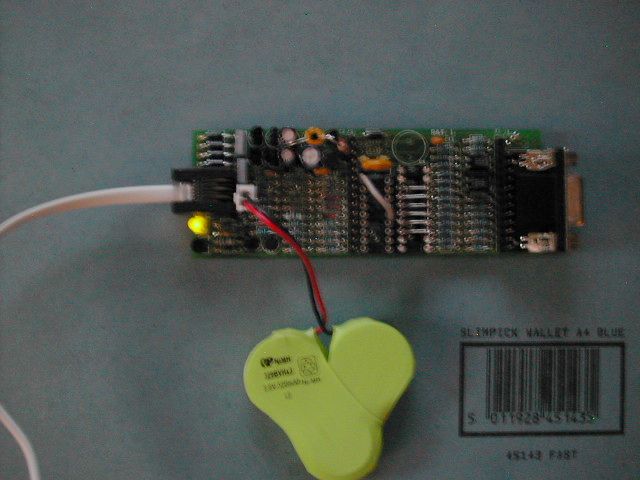
Make sure the battery is plugged in correctly!!
Also check the voltage across the battery - it should be at least 3.6V. If it is any less you will need to recharge the battery for several hours using a power supply set to 4.0V output, 30mA max.
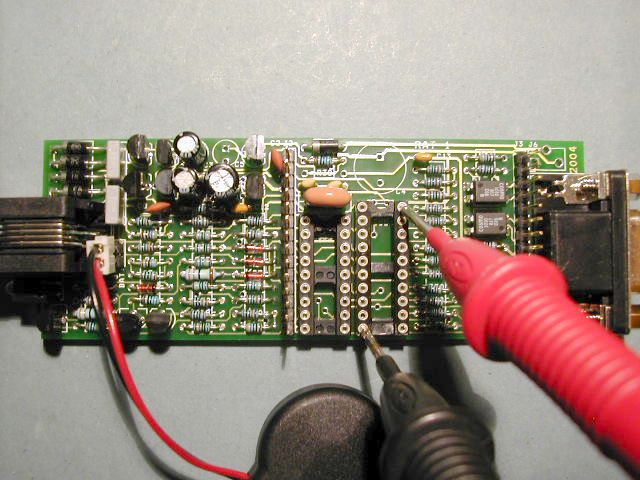
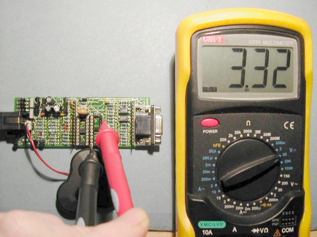
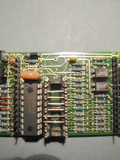
Check that the voltage regulator IC1 is working correctly using a DVM. You should have about 3.3V measured between pins 10 and 20 of the IC5 socket. See photo.
If you don't get 3.3V check the battery voltage and that zener diode D5 has been fitted correctly.
This allows B0 and B7 to be use for interrupts and B1 to B6 to be used to generate the DTMF and modem tones.
The following tests will involve plugging the RAT_1 into a suitable phone line.
As a precautionary first step, use a 24V bench power supply to simulate the line, and connect a 1K 2W resistor in series with the positive lead of the supply.
Either use a salvaged phone cord, or connect temporarily to the RJ11 phone connector using pins 3 and 4 (the middle 2 pins) by soldering suitable lengths of wire to the pins. Polarity does not matter because of the front end bridge rectifier.
Plug the phone line (or 24V simulated line) into the RJ11 phone line connector.
When RAT_1 is on-hook very little current flows from the line. The only current to flow should be through the 1M ohm resistor R6.
With 24V applied froma bench power supply, measure the voltage across the 1K line resistor. You should get between 18mV and 22mV. Any more than this and you may have a problem.
The hooksitch is a 2 transistor circuit which is used to connect RAT_1 to the phone line.
Normally the PIC controls the hookswitch, but we can do it manually just to test the circuit.
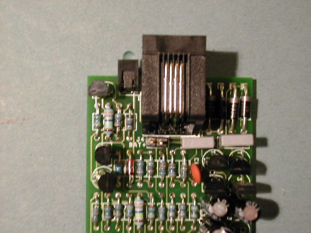
Use a short length of wire (shown grey here) and make a temporary connection between Pin 1 and pin 14 of the PIC socket.
The LED should glow brightly whilst the wire is connected and go out when the connection is removed.
If any problems - see below in Troubleshooting.
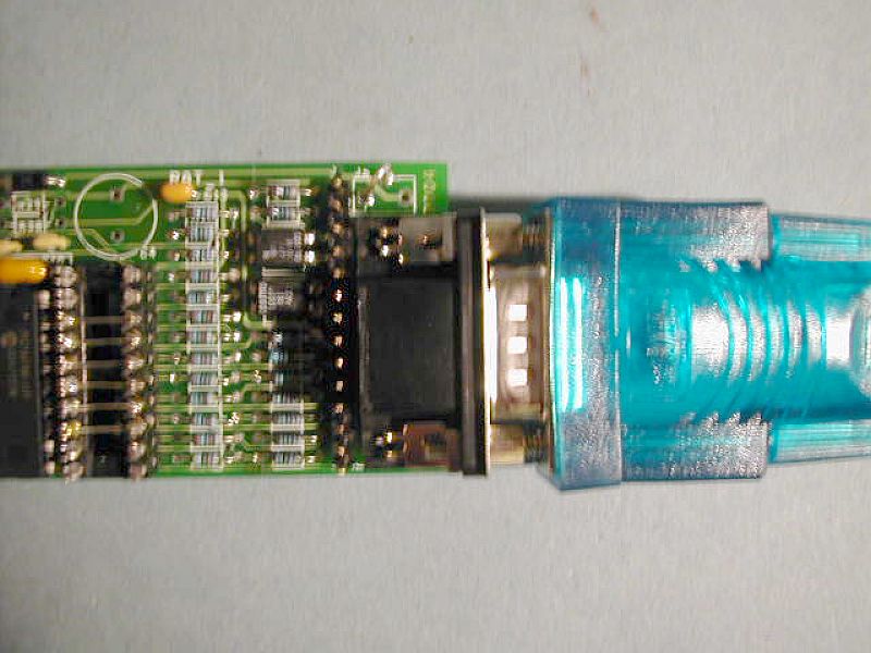
At this stage you can also plug the PC serial cable into here for the PC_Link
Make a small test loop - a 5mm U shape from the thicker component leads found on the 1N4004 diodes. Solder it into the back and side holes of J6 as shown opposite.
We are now ready for final tests: Insert the PC serial port plug and reconnect the line simulator.
All sent in CAPITAL letters!
O - Go Off-Hook
H - Hang-Up
D - Go off-hook and dial the number from ROM
T - send a 2100Hz Answer Tone
P - send a series of short tones (pips)
M - Send a V23 message from ROM
S - Send some 75 baud modulation
V - Enter Voltmeter mode
......... Exit Voltmeter mode.
After typing "O", digits 0 to 9, * and # can be entered from the terminal and will be dialled to the line.
Remote Access RAT_1 V1_88_D
Remote Access
>
If this does not happen, check the settings of the terminal program first - if you see garbage characters, then the baudrate may be set incorrectly. Check that you have connected to the right Com Port!
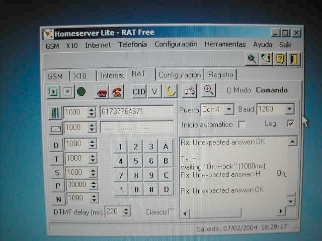
Homeserver Lite (RAT Free) shown opposite is distributed free with the RAT_1 kit.
It provides the ability to select the serial port and the baud rate, control the hook-switch using the red telephone buttons, and dial digit strings automatically from the PC via the RAT_1.
Additional buttons execute the Dial D, Tone T, Slow Modem S, Pips P and Nickel Tones N commands.
Further code is under development to allow messages to be send between RAT_1 units and the PC.
The RAT_1 is a relatively simple design but there are always likely to be some problems when dealing with the voltages and signals associated with telephone lines. Here are some somple checks to make to ensure your RAT_1 kit works. Supply the unit with 24V from the bench supply and a 1K line resistance.
1. Having built the kit ensure that all the transistors and diodes are fitted in the correct position and with the correct polarity. MPSA42 and MPSA92 transistors are easy to get mixed up. The MPSA 92 devices are fitted it positions T1 and T7 - closest to the top edge of the board. The MPSA 42 parts are in positions T2 and T6 - further in towards the middle of the board. Check this before you apply power to the pcb.
2. If the hook-switch test does not work, first check that you have 3.3V on pin 14 measured between pin 14 Vcc and pin 5 0V. Then carefully check that T1 and T2 are correctly fitted. Check the values of R1 (4K7), R9 (100K) and R2 (100K). Use the layout sheet to confirm the component locations. Use the resistance measurement ranges on your multimeter to check the resistor values.
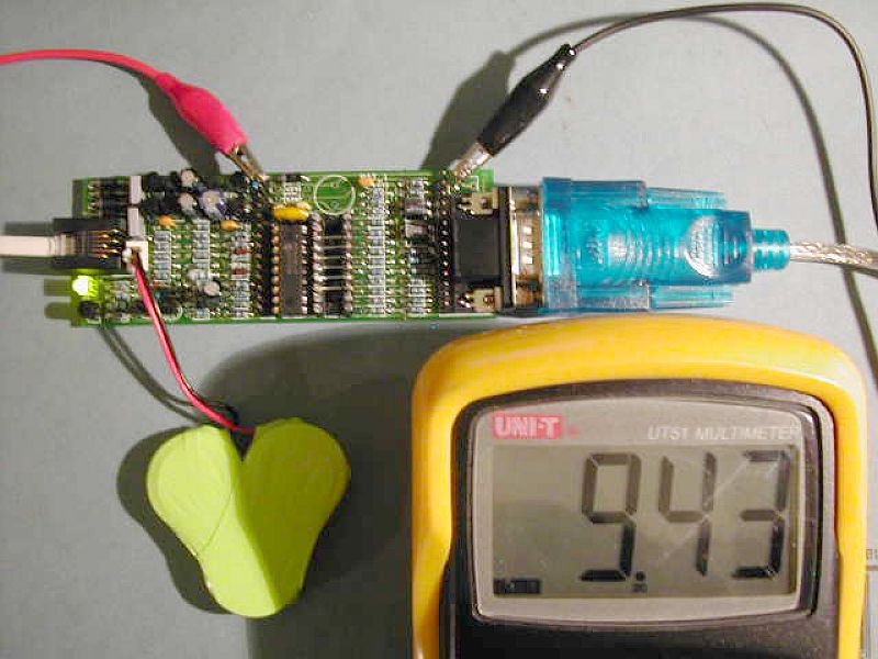
With the RAT_1 connected to the 24V line simulator:
Clip the positive of your meter to Pin 1 of the expansion connector J2, and the negative to the new earth clip as shown.
The meter shows the voltage between the "Audio" signal pin and 0V, when the unit is off-hook. Note the brightly glowing LED.
If the hook switch T1 and T2 is working correctly then almost 10V is measured when RAT_1 is powered by the 24V line simulator.
When supplied by 24V with a 1K line resistor, there should be about 0.42V across R47. The current = 420mV/47R = 8.9mA. Check the voltage across R7.
5. Put the positive probe on the positive of the LED and the negative on the 0V test clip. When offhook, the LED anode should be at about 5.9V.
6. The battery is nominally 3.6V but fully charged can rise to about 4.2V. Zener diode D5 prevents the battery voltage ever going above 5.1V. Check again that D5 is fitted corrrectly. If in backwards it wil "crowbar" (short circuit) the Vraw rail and the battery and the voltage regulator will not be able to supply 3.3V.
7. If the battery voltage is above 3.5V then the output of the voltage regulator should be 3.3V. If it is much less than 3.3V ther is something shorting the Vcc rail. Look for solder shorts or badly soldered components.
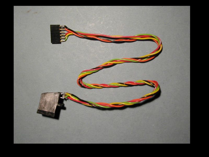
This is the ICSP programming cable made up to connect to RAT_1 for upgrading the firmware.
A 6 pin SIL connector carries the ICSP signals:
Pin 1 0V Black
Pin 2 /MCLR Orange
Pin 3 No Connection
Pin 4 Vcc Red
Pin 5 Port B6 (Clock) Yellow
Pin 6 Port B7 (Data) Green
The ICSP lead plugs directly into the expansion header J3 - but NOT when the phone line is connected.
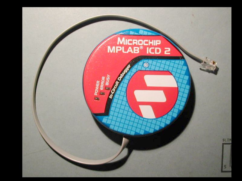
This plugs into the PC either by RS232 or USB and allows PIC devices to be programmed and debugged in circuit.
The ICD 2 is relatively low cost (about $200) and should be considered an essential bit of equipment for the serious embedded firmware engineer.