The Origins of the Transferator.
Back in 1977, John Bourne of Fareham, Hampshire, UK proposed the use of a lightweight open ended cup to take the place of the normal displacer in a beta type Stirling engine. He called the is the "Transferator" as he proposed that it was working both as a gas transfer component and a regenerator.
One of the advantages was that it allowed the overall height of the engine to be shortened because the cooler could now be packaged inside the hollow volume of the transferator. Secondly, because the transferator was an open component, there would be no pressure acting on it so it could be made very lightweight - John used a section of a beer can running inside a stainless steel sugar bowl.
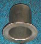
I have now taken the idea of the lightweight transferator and substituted it in place of the more conventional displacer in a Manson type engine. Fig 2. above. The transferator can be a simple open ended stainless steel cookware container.
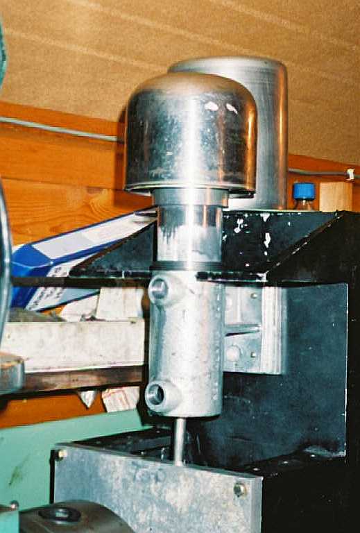
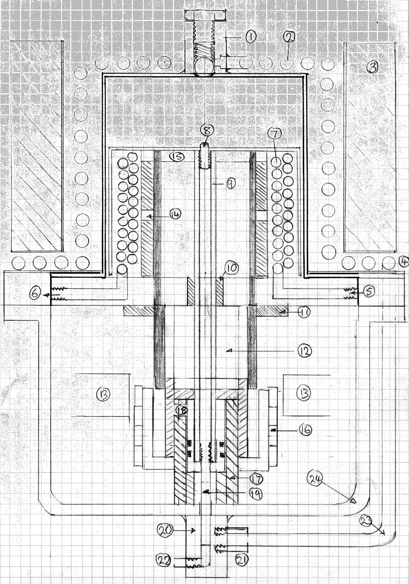
I also propose the use of an "external type" sleeve piston, as a means of reducing the reciprocating mass within the Manson engine. Se Fig 3. below.
In addition, the aluminium sleeve will expand at a greater rate than the steel stanchion tube and so the engine will not bind if overheated.
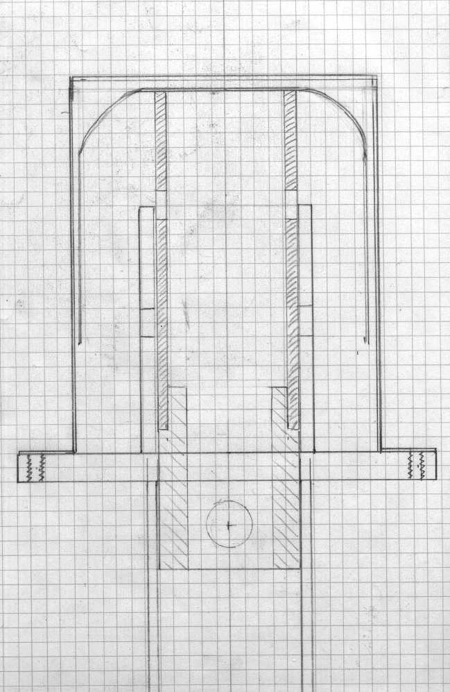
The aluminium sleeve piston has an upper and lower port drilled which communicates the internal working gas space with the buffer space at TDC and BDC.
The cooler is a double layer coil of 3/16" copper brake line tubing. An additional development is the use of an external heater tube asssembly made from stainless steel tubing in order to increase the heater surface area.
In this design the engine has internal water cooling coil placed around the working cylinder and arranged in such a way as to come into good contact with the working gas. This maximises the cooling effect and so the suction stroke produces a better pressure difference.
An internal baffle tube, cut from a tin can, ensures that the expanded gas is directed over the cooling coils before being vented from the engine.
A heatshield is used between the hotcap and the air cooling fins to prevent direct shorting of radiant heat to the cold section of the engine. Similarly the inside base of the transferator pot has a disc of insulating material fitted to it to prevent heat conduction from the transferator straight down the power piston. Ceramic board or other high temperature material may be used for this.
One potential way of improving the Manson engine is to increase the surface area of the heater. This may be done using either of the two common techniques used by the Stirling engine community, either heater tubes or fins.
Heater tubes sub-divide the air into many smaller volumes and pass these through narrow bore tubes, where the outer surface area to internal volume is a more favourable ratio than a plain heater head.
The use of fins will increase the overall surface area of the head by perhaps a factor of 3. There is always a trade off between the heater efficiency and the ease (and cost) of manufacture. Fins need to be milled into the heater head and tubes need to be individually welded in place - both operations add to the complexity. Casting finned heater heads in aluminium bronze or stainless steel would be attractive for large scale manufacture.
With the Manson there exists another possibility, because the cycle is effectively controlled by the sliding motion of the piston acting as a simple combined inlet and outlet valve. The valve effectively isolates the working volume of the engine from the atmosphere during the expansion and suction phases of the stroke, a small volume of air being admitted or released from the engine at TDC and BDC respectively. The valve is an effective means of shutting off the engine from otherwise dead volume and so could be used to our advantage in isolating, for example, the working volume from a more efficient heater, but one which contains significant dead volume.
This is where the Manson engine could benefit from the Flash steam fraternity and their monotube boilers. Instead of heating water to flash steam in a simple wound coil of tubing, a small bore monotube could be used as an efficient air heater for the Manson.
The exact arrangement for achieving this will be explained in a later posting.
The power output of this engine is proportional to the mean effective pressure (MEP) acting on the surface area of the piston. The larger we can make the heating and cooling effects, the larger the MEP.
A very early prototype using plain aircooled section showed pressure swings of about 0.5 psi either side of atmospheric pressure. With greater ration between heating and cooling surface areas and the internal swept volume of the engine, this figure should be improved significantly.
Pressure swings can easilly be measureed using a water tube manometer and if a 10m water column can be supported by atmospheric pressure (14.7 psi), then a 2m or 6' column represents a pressure swing of approximately +/- 1.5 psi - a size which could be conveniently fixed to the workshop wall.
Simulations have shown this type of engine should be capable of about 5W of shaft power running at atmospheric pressure. This equates to approximately 0.2W per cc of power piston swept volume.
Using relatively simple construction it should be possible to build a Manson engine of some 300 to 500W shaft power, heated by a wood burning stove or other suitable heatsource. The efficiency of this engine is likely to be around 5%. Air preheating and re-utilisation of the hot exhaust withing the burner could be used to increase the overall system efficiency.
With this in mind I have a 10" (250mm) diameter stainless steel cooking pot waiting in my workshop, already fitted with a sealing flange and aluminium baseplate, ready to accept a 4.5" diameter working piston. More on this later.
Further improvements in efficiency could mede by using an annular regenerator placed in the space between the transferator and the outer hot-cap.. Alternatively the regenerator could be made in the form of a "pancake" attached to the top of the transferator and similar in nature to the Robinson engine regenerator.
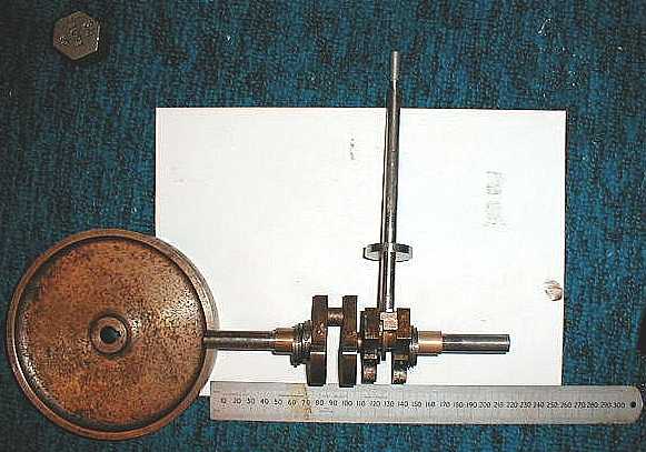
Work has now started on an experimental engine, to be used as a test-bed for some of the above ideas. Recently obtaining a ready made crankshaft with a 3/4" throw from a model engineering show, inspired me into action and build an engine of 1.5" (38mm) stroke and 2.08" (53mm) bore using the transferator principle.
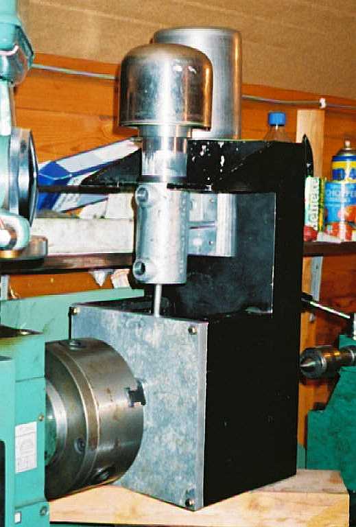
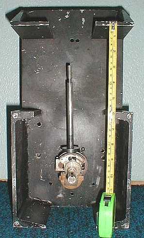
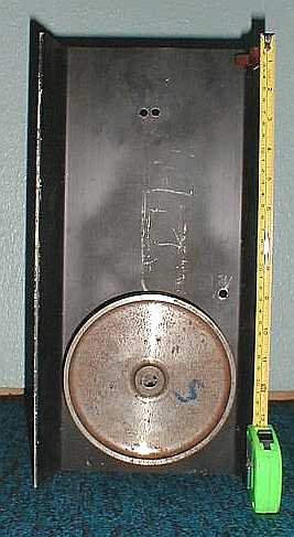
The mechanical half of the engine is now largely complete with crankcase, crankshaft, working cylinder, piston and gudgeon pin all assembled. The engine was mounted with the end of the crankshaft in the lathe chuch, enabling it to be "motored" at slow speed, with plenty of lubricating oil in order to run-in the bearing surfaces, piston and bore.
The main remaining task is to assemble the components which make up the heater head and the heat-exchangers.
The cooler is a 16' (6m) length of copper brake tubing wound in a double layer coil approximately 3" (76mm) in diameter. The heater is an 18' (6m) length of 316L stainless steel 6mm OD tubing wound into a 5" diameter coil, placed in the hot gas flow around the hot cap.
The baseplate is a 6" diameter (152mm) disc of 3/8" (10mm) aluminium. The heater "Top-hat" and the cooler coils are both secured to this baseplate.
The Cooler connections are of the threeaded brass bulkhead type tube fittings and pass through the baseplate and help to keep this lower end of the engine cool. The copper cooler coil is wound in close proximity to the baseplate.
The transferator is a cut down stainless steel bowl, 3/4 quart size. It is secured to a 48mm diamter piston extension tbe made from stainless steel and fitted with an insulating washer to help prevent heat loss through the transferator straight down the aluminium piston tube.
The heater is a 5" (127mm) diameter coil of 6mm OD 316L stainless steel pipe wound into a 10 turn openly spaced coil. Beneath this coil is a 8" diameter stainless steel pan lid which acts as a heat break and prevents heat loss from the burner to the lower half of the engine.
The burner will initially be propane of the tangentially fired "cyclone type" The burner will be enclosed in an air preheater and will use a 2" diameter flue pipe.
I hope to have a sketch of the overall arrangement on this site in the next few days.