This is, without a doubt, the single most worthwhile upgrade for these mills. Since they only measure absolute table movement, not only do they make backlash in your leadscrews irrelevant, but it also eliminates the need to deal with those weirdly graduated handwheels and a lot of math. They also eliminate the chance of error when you are trying to measure over a long distance.
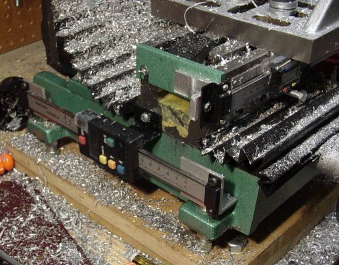
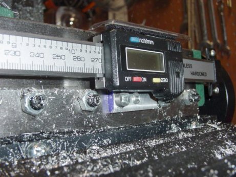
I bought these from CalAero Supply. These are, I believe, made in China or Taiwan, and are similar to others sold elsewhere. The "X" axis DRO is the 12" model, and the "Y" axis DRO is the 8" model. I believe I spent about $150 for the pair. They can both be zeroed out at any point, but only the 12" scale holds its position even when it is turned off. The 8" scale will revert to zero when you turn it off and back on. Both of them have an output port for a remote display, which is nice, but for $300 I figured I could make do without one for a while.
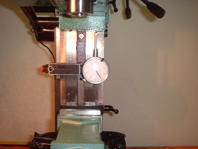
For my projects I needed the X and Y DRO's more than a Z-axis DRO, but others would suggest getting the Z axis DRO first. The Z axis on this mini-mill is very hard to accurately measure, due to its awful backlash and awkwardly placed handwheel. Personally I get by fine with a dial indiator on a magnetic mount. When I need to make a precise depth of cut, I slap on the dial indicator and go for it.
Many mini-mill owners install their X-axis DRO on the back of the table, which is easier than trying to make it fit on the front. There are no gib screws or other stuff to interfere with it on the back of the table, but you will need a remote display for it then. I decided to mount mine on the front of my table. The only thing that's a problem here is that you must extend or move the gib lock lever, as there isn't enough room to use it under the DRO.
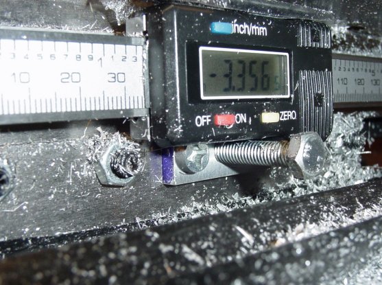
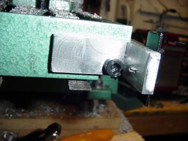
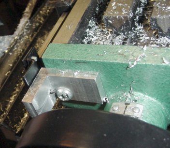
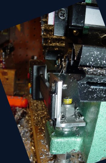
The brackets for the "X" axis were milled from billet aluminum, and use the existing holes in the end of the table.
The readout is fastened to a milled bracket that is bolted to the saddle using the hole for the scale pointer. The bolt you see is a temporary replacement for the gib lock (until I rig up something better.)
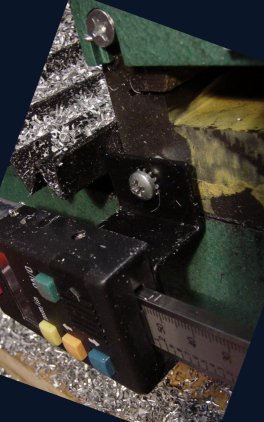
The brackets for the "Y" axis are simply aluminum angle iron that are fastened to the mounting rods that support the mill.
The readout is fastened using its included bracket to the saddle, where I had to drill and tap a hole -- easy to do in cast iron.