MATERIALS:
The base was made of 1x4 clear pine.
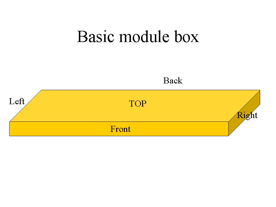
There are 2 pieces of 1x4 clear pine 48 inches long (Front & Back), and two pieces about 22 1/2 inches long (Left and Right).
The top is a piece of 1/2 inch thick, 5 ply ACX plywood, 48 inches long and 24 inches wide.
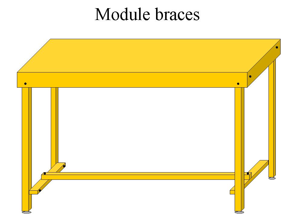
The legs are straight 2x2s 45 inches long.
The braces are 1x2s cut to described length.
The backdrop is cut from a piece of masonite 48 inches long and 24 inches wide.
The fascia is cut from a piece of masonite 48 inches long and 14 inches wide.
Two inch course thread dry wall screws are used as permanent fasteners.
Various length #10 32 bolts with wing nuts and washers are used as the removable fasteners.
The module landform surface was created with a 2 inch thick 48x24 inch piece of white styrofoam (pressed beads).
Carriage bolts, paint, assorted hardware and power strip as described in the HOn30 standards.
Standard 1/2 inch thick Homasote roadbed, HOn2 1/2 track, track nails, switches and switch stands (as required).
Standard water soluble scenic materials.
ASSEMBLY:
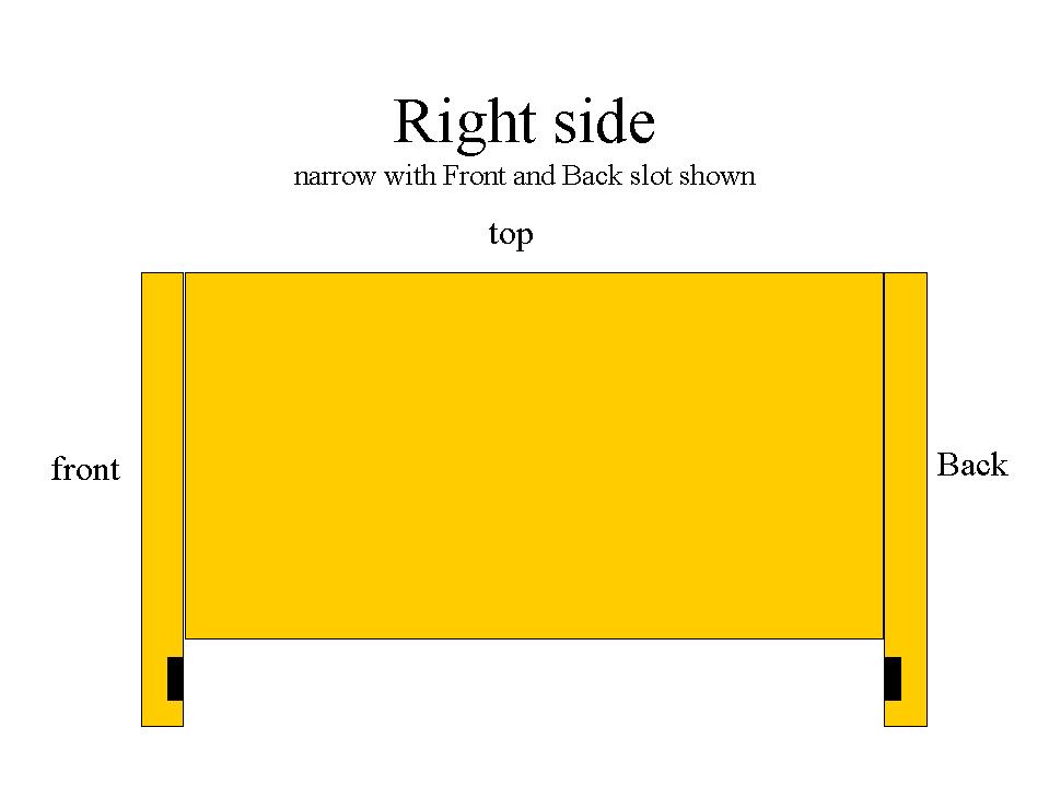
The 'Right' side board was trimmed to 3 inches in width.
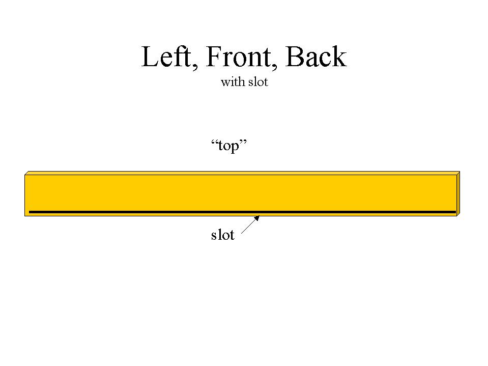
The 'Left', 'Front' and 'Back' boards have a slot cut 3 1/4 inches from the "Top" side. The slot is 3/8 inch deep. The slot needs to be wide enough for the masonite backdrop to slide into for storage.
'Right', 'Left', 'Front' and 'Back' are screwed securely together with 2 inch long dry wall screws to make a square or open sided box. A 1/2 inch thick, 5 ply piece of plywood 48x24 is screwed to the 'Top' side of the box.
The masonite backdrop is trimmed to 23 1/4 by 47 1/2. When stowed for shipment, this slides into the slot in the 'Left', 'Front' and 'Back'.
The legs:
The legs are 2x2x45 with a 2 1/2 carriage screw in the bottom for height adjustment. Holes are drilled in the module to match the holes in the center line of the leg. 3 inch #10 32 bolts with wing nuts and washers hold the module to the legs.
Bracing:
The legs are braced 3 inches from the bottom. The right front leg is braced to the right rear leg with a 1 x 2 x 22 1/2 board. The left front leg is braced to the left rear leg with a 1 x 2 x 22 1/2 board. A hole is drilled in the center of each left and right brace. This hole matches the holes in the 1 x 2 x 42 1/2 cross brace. This is all attached together with 2 1/2 inch #10 32 bolts with wing nuts and washers. This brace from the top view looks like a very WIDE H suspended 3 inches from the ground.
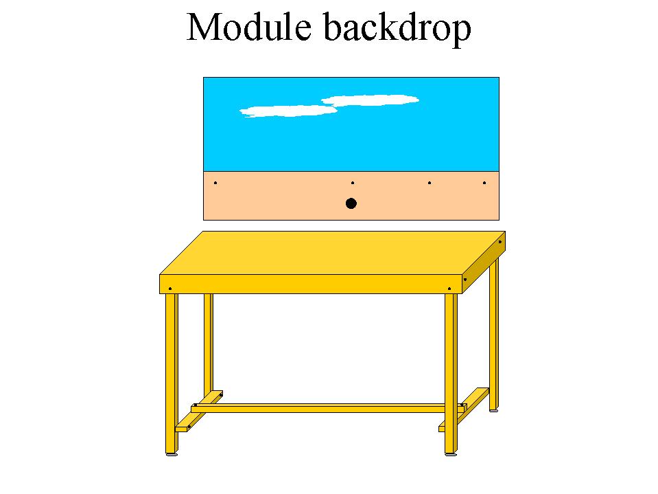
The Backdrop:
The top of the backdrop is specified as being 14 inches above the rail. I used a 1/2 inch thick homasote rail bed and approximated the rail to be 1/10 of an inch above the homosote. A line was drawn 14.6 inches from the "TOP" of the 23 1/4 by 47 1/2 masonite. A primer coat of flat white paint was followed by two coats of Sears D125 flat blue. After the paint has dried and cured draw a vertical center line on the BACK side of the masonite (the non-blue side). The vertical center line should be about 23 3/4 inches from the edge of the masonite.
A three quarter inch diameter hole was drilled in the masonite 19 inches from the 'TOP' of the masonite and on the vertical center line (23 3/4 inches from the edge). This finger hole is needed to help slide the stowed masonite out.
To mount backdrop:
Drill three holes in the masonite 17 inches from the 'TOP', 6 inches from the 'left' side, the 'right' side and on the vertical center line. A fourth hole was drilled on the "right" side to allow the power strip to be mounted on the back side of the module, 6 inches from the "right" side. The center hole is used to secure the power strip stress relief clamp. Center the Backdrop on the back of the module, making sure the backdrop is square and level. Clamp the backdrop to the back of the module box. Run your drill bit through the previously drilled backdrop holes.
Secure with 1 1/2 inch #10 32 bolts with wing nuts and washers.
Fascia:
The fascia was less than 12 1/2 inches in height from the highest point of the scenic contour to the bottom of the fascia. The fascia is a maximum of 46 1/2 inches long. This allows the fascia to be packed to fit between the "leg" bundle and the back edge of the box. To meet both Left coast fascia color requirements (Hunter Green) and National HOn30 fascia color requirements (Flat Black), the fascia scenic contours are "reflective".
In order to mount the fascia on the module, drill three holes in the masonite 2 1/2 inches from the "Top" of the module plywood top, 6 inches from the "left" side, the "right" side and on the vertical center line. Secure with 1 1/2 inch #10 32 bolts with wing nuts and washers.
Control Panel:
The control panel is an 8 x 8 inch square of 18 gauge aluminum. It is painted flat black with a flat white track plan showing rail gaps for electrical isolation. Cab control is indicated by 1+ inch color dots. The switch has a center off position. The control panel is attached to the fascia by two screws on the vertical center line of both the control panel and fascia. The control panel hole in the fascia was cut to allow the fascia vertical center line hole to support the control panel. A second hole was drilled on the center line of the fascia to match the control panel.
The bolt heads were painted flat black on the fascia and control panel.
The 'front' edges of the module box that are exposed should be painted flat black since the fascia does not cover the entire width.
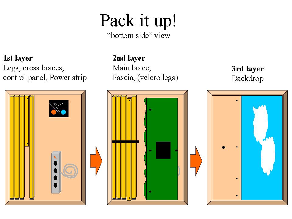
TO PACK:
See drawing
Disassemble fascia, control panel, control panel switch(es), backdrop, power strip, legs, cross braces.
1. Secure bolts, washers, wing nuts as a subassembly to reduce loss potential. Put bolts in a bag.
2. Minimize carriage bolt length on legs.
3. Insert legs, left and right brace and cross brace into module box. The left and right brace, slip end to end next to the legs and the cross brace slips over the L/R braces in module box. Secure with velcro strap.
4. Insert control panel, painted face down in module box. Secure in place with wood screws through mounting holes to inside surface of plywood "top" of module box.
5. Secure power strip in place with wood screws through mounting holes to inside surface of plywood "top" of module box. Cable stress relief goes into bag with screw sub assemblies. Velcro power strip cable into a bundle.
6. Place fascia into module box with flat black side to power strip cable bundle.
7. Slide backdrop into module box slots with Blue side out. This protects the blue sky from any damage from any items that might work loose inside the module box.
Insert module box into shipping crate.