GumBot
Creating, Executing and Saving GumBot Programs
Introduction
The goal of GumBot is to allow the user to manipulate binary outputs to behave in whatever way he/she wants simply by drawing diagrams consisting of interconnected blocks (these diagrams we will refer from now on as “GumBot programs”).
There are several types of blocks (more on blocks here) that represent different operations, such as reading from inputs, writing to outputs and counters that count down. You will find that there are very few types of blocks currently available and each performs just the most basic of operations. This is partly due to my own laziness, but mainly it is to keep the interface simple. The idea is for users to combine these basic blocks into increasingly more complex blocks themselves to perform tasks they really require. (Admittedly, there are things that GumBot programs simply cannot do with the current set of blocks, no matter how the blocks are arranged.)
The programming interface consists of a menu bar, toolbar and a work area and looks something like this:
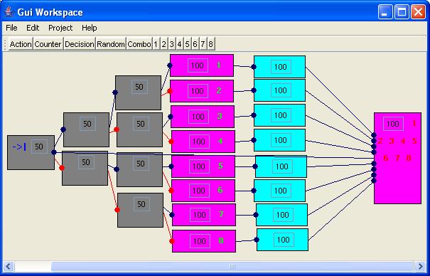
GumBot currently includes a simple simulator window that simulates the inputs and outputs. To actually read from or write to one of the computer’s I/O ports, you will need to modify the read() and write() methods in IOHandler.java (more on this here).
Creating, Executing and Saving GumBot Programs
To create a new GumBot program, choose File -> New. This will clear the work area of any blocks. You can then create your GumBot program by drawing and connecting blocks. To run a GumBot program, choose Run -> Start. Choose Run -> Stop to stop a currently executing program. To save a GumBot program, choose File -> Save. GumBot programs are saved as XML files. Saved programs can be opened for editing and execution by choosing File -> Load.
Blocks
Blocks represent the different operations that are performed when a GumBot program is executed. Each block can connect to up to 2 other blocks, which I call its “Next Block” and “Alternate Next Block”. The connection to the “Next Block” is shown as a blue line with a circle at the “Next Block” end. Similarly, the connection to the “Alternate Next Block” is shown as a red line with a circle at the “Alternate Next Block” end. During execution, once GumBot has finished performing the operation associated with a block, it moves on to either its “Next Block” or “Alternate Next Block”.
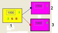
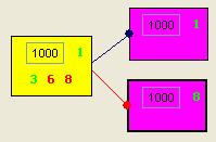
In the above example, block 1 has block 2 as its “Next Block” and block 3 as its “Alternate Next Block”. Block 1 is a Decision Block (see description below), which means that GumBot will proceed to block 2 if the condition associated with block 1 is met. Otherwise, it will to block 3 instead.
Drawing and Connecting Blocks
To add a block to the work area, click on the corresponding button on the toolbar. You can then drag the block to the desired location. A copy of a block can be made by selecting it and then choosing the “Clone” item under the “Edit” menu.
To connect one block to another, just click on the first block once and then click on the second block. If the first block isn’t already connected to any other block, the second block becomes the “Next Block” of the first. Else, it becomes the “Alternate Next Block”. Clicking on a block twice will remove its connections to other blocks. Connecting blocks in this way is still a bit fiddly and might take some getting used to as it is quite easy to accidentally create connections when you don’t mean to. Alternatively, you can right click on the blocks concerned to display a popup menu and choose items “Set Source”, “Set Target” or “Set Alt. Target”.
Action Block

An Action Block sets the binary outputs individually either ON or OFF. The “1000” in the box defines a delay, in milliseconds, before moving to the next / alternate block, but after the outputs have been set. This delay can be edited directly. The numbers in green or red signify the outputs to be set ON or OFF. Green means set the output ON, red means set it OFF. To add an output to the Action Block, click on the corresponding number on the toolbar and then click on the Action block. Doing this again for an output that has already been added will remove it from the Action Block. The default state of the newly added output is ON. To toggle between ON and OFF, click on the number corresponding to the output on the Action Block.
Decision Block

A Decision Block reads the states of the 8 binary inputs and compares them with the condition set for this block. If the condition is met, the program follows the blue path to the “Next Block”. If the condition is not met, the program follows the red path to the “Alternate Next Block”. The “1000” in the box defines a delay, in milliseconds, before moving to the next / alternate block. This delay can be edited directly. The numbers in green or red signify the inputs whose states make up the condition to be tested. Green means the input is ON, red means it is OFF. To add an input to the Decision Block, click on the corresponding number on the toolbar and then click on the Decision block. Doing this again for an input that has already been added will remove it from the Decision Block. The default state of the newly added input is ON. To toggle between ON and OFF, click on the number corresponding to the input on the Decision Block.
The example below performs the following – “if inputs 1 and 3 are ON and inputs 6 and 8 are OFF, wait 1000 milliseconds then set output 1 to ON. Otherwise, wait 1000 milliseconds then set output 8 to ON”.
Counter Block

A counter block holds a counter which decrements by 1 each time the Counter Block is entered. The ‘10’ in the box defines the initial value of the counter. This value can be edited directly. If the current value of the counter is greater than 0, the program follows the blue path to the “Next Block”. Once the counter reaches 0, the program follows the red path to the “Alternate Next Block”. The counter is then reset to its initial value.
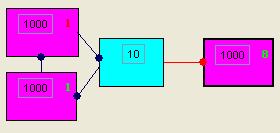
The example below performs the following – “toggle output 1 ON and OFF 10 times, then set output 8 to ON”.
Random Block

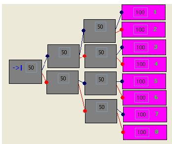
A Random Block randomly routes the program either down the blue path to the “Next Block” or the red path to the “Alternate Next Block”. The ‘50’ in the box defines the percentage probability of the program following the blue path to the “Next Block”. This probability can be edited directly.
The example below performs the following – “randomly set one of either outputs 1, 2, 3, 4, 5, 6, 7 or 8 to ON with equal probability”
Combo Block

A combo block is a combination of other blocks. When creating programs that do anything more than basic tasks, you’ll probably find that the GUI becomes cluttered pretty quickly. You can group multiple blocks that together perform a task into a single Combo Block and so save a bit of space. Combo Blocks are also useful in that they make re-use possible. You can define Combo Blocks for commonly occurring tasks and use them in different programs or in different places within the same program.
Defining Combo Blocks
You define a Combo Block in much the same way as you would create a program, i.e. draw the constituent blocks and connect them. Additionally, for the Combo Block, you should define an entry point, exit point and alternate exit point. These are the points from which the Combo Block connects to other blocks. Below is an example of how a Combo Block would be defined:
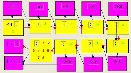
The markers ->|, |-> and |->> identify entry, exit and alternate exit points respectively. To mark a block as an entry, exit or alternate exit point, select the block and then choose the corresponding item under the “Edit” menu. The above example implements a delay that varies in 100ms increments from 0 to 25500ms depending on which inputs are ON.
Once defined, you can save the Combo Block by choosing File -> Combo -> Save and assigning it a suitable name. To edit a Combo Block, choose File -> Combo -> Load.
Using Combo
Blocks
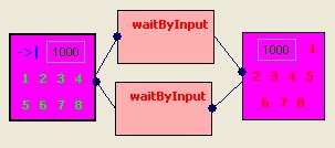
Once a Combo Block has been saved, it can be used in a GumBot program by clicking the “Combo” button on the toolbar and then choosing it from the list of available Combo Blocks. The example below uses the Combo Block defined above to do the following – “flash all the outputs ON and OFF at a rate dependent on the value of the inputs. Stop if all the inputs are OFF”.
Input and Output
GumBot reads from inputs and writes to outputs by calling the read() and write() methods of the IOHandler class.
Currently, IOHandler is implemented to display a simple dialog to simulate the 8 binary inputs and outputs. The 8 boxes represent the 8 outputs and each box will change colour to yellow if the corresponding output goes ON. The numbers 1 to 8 represent the 8 inputs. To toggle an input ON or OFF, click on it. Red means the input is OFF. The outputs can be arranged in a row (basic view) or as a 7-segment display by choosing the appropriate item from the popup menu that appears when you right click on the dialog.
To make GumBot actually read or write from one of your PC’s I/O ports, you will need to rewrite IOHandler’s read() and write() methods with your own implementation (For example, you can get tips on how to access the parallel port at Juan Gabriel Del Cid’s website here).
The code for the IOHandler class (IOHandler.java) is included in the GumBot download. Once you have modified the IOHandler code, compile it and the copy the resulting IOHandler.class file into the client directory along with the other class files. Anyway, do please get in touch with me if you need help doing this.
Download GumBot
To install, just download the zip file from the link below, and extract its contents into one directory. To run GumBot, run the batch file "GumBot.bat". You will need Java 1.2 or later to run GumBot. Just so I'm covered, please read and understand the following License Agreement before downloading:
GumBot version 0.10 is free software. You may freely use, copy and distribute it. However, you may not decompile, disassemble, reverse engineer or modify GumBot or any part of it. It is provided 'as-is', without any express or implied warranty. In no event will the author be held liable for any damages arising from the use of this software.
Accept the above terms & download GumBot
Feedback
Admittedly, GumBot is far from being the finished product. GumBot’s many quirks and bugs notwithstanding, GumBot programs are still quite limited in what they can actually do. The reason I am posting it here anyway is that I would very much welcome feedback on how to proceed with its development, if at all. Top most on my list of want-to-knows is whether there is anyone out there who would actually want to use an application like GumBot. Next are suggestions for improving it, especially on the kind of new blocks to be added.
Anyway, if you have anything to say about GumBot (praise, criticisms, suggestions, etc) please do send me an email.