This page shows my experiments with various LOPT's and High voltage transformers and related electronic drivers.
Corona discharge may look nice, but please avoid prelonged exposeure to the gas in confined places, as Ozone is oxygen depleting and also forms harmfull fluids on the surface of the lungs. Also there is a a high ammount of UV radiation and possibly X-radiation from metals used in the electrodes. Have fun be safe.
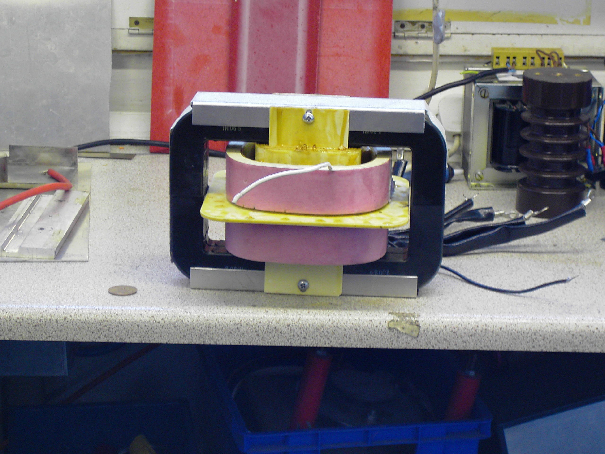
Origionaly made for Sherman Treaters of Thame, This 10KW rated 25khz LOPT transformer is designed to be used on a corona treatment machine, to treat plastics before the printing stage. The treatment process allows the plastic to attain proporties that allow inks to adhear to its surface. Measurement for this is the Dyne level. Special inks and pens are availible to perform the test.
As the availibility of infomation on the previous drive unit is almost impossible to attain, i had to make my own Inverter to change 400V DC into alternating squarewave at 18Khz. I have now made a reliable inverter that doesn't destroy all my mosfets and IGBT's that i use, and incorporates a resonant stage in series with the transformer. I also used a current trip on the feed to the transformer so as to cut out in the event of an over current condtion.
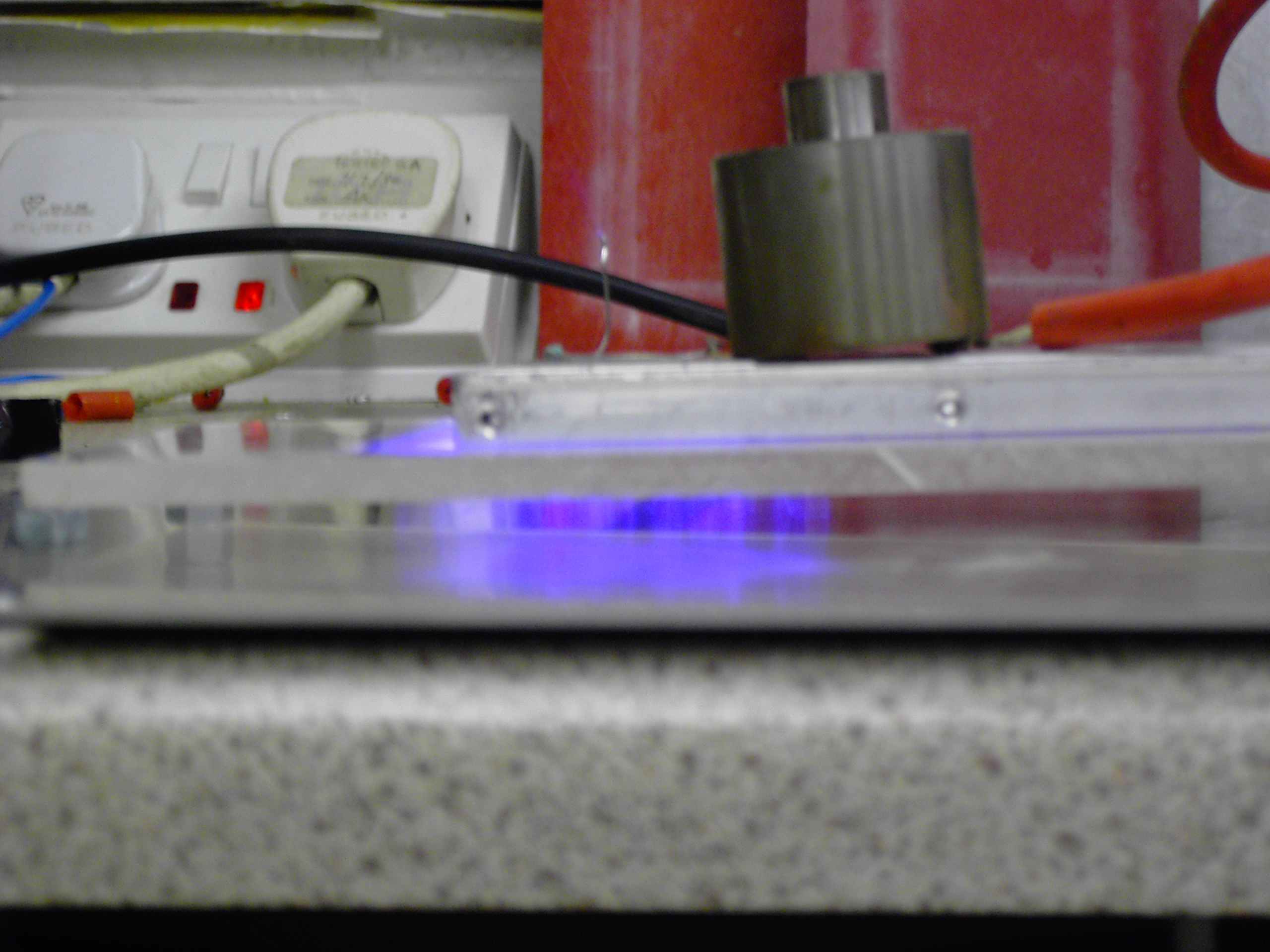
Left: Corona between perspex and aluminum baseplate, HT plate is aluminum and is aprox 1 cm from earthed base plate.
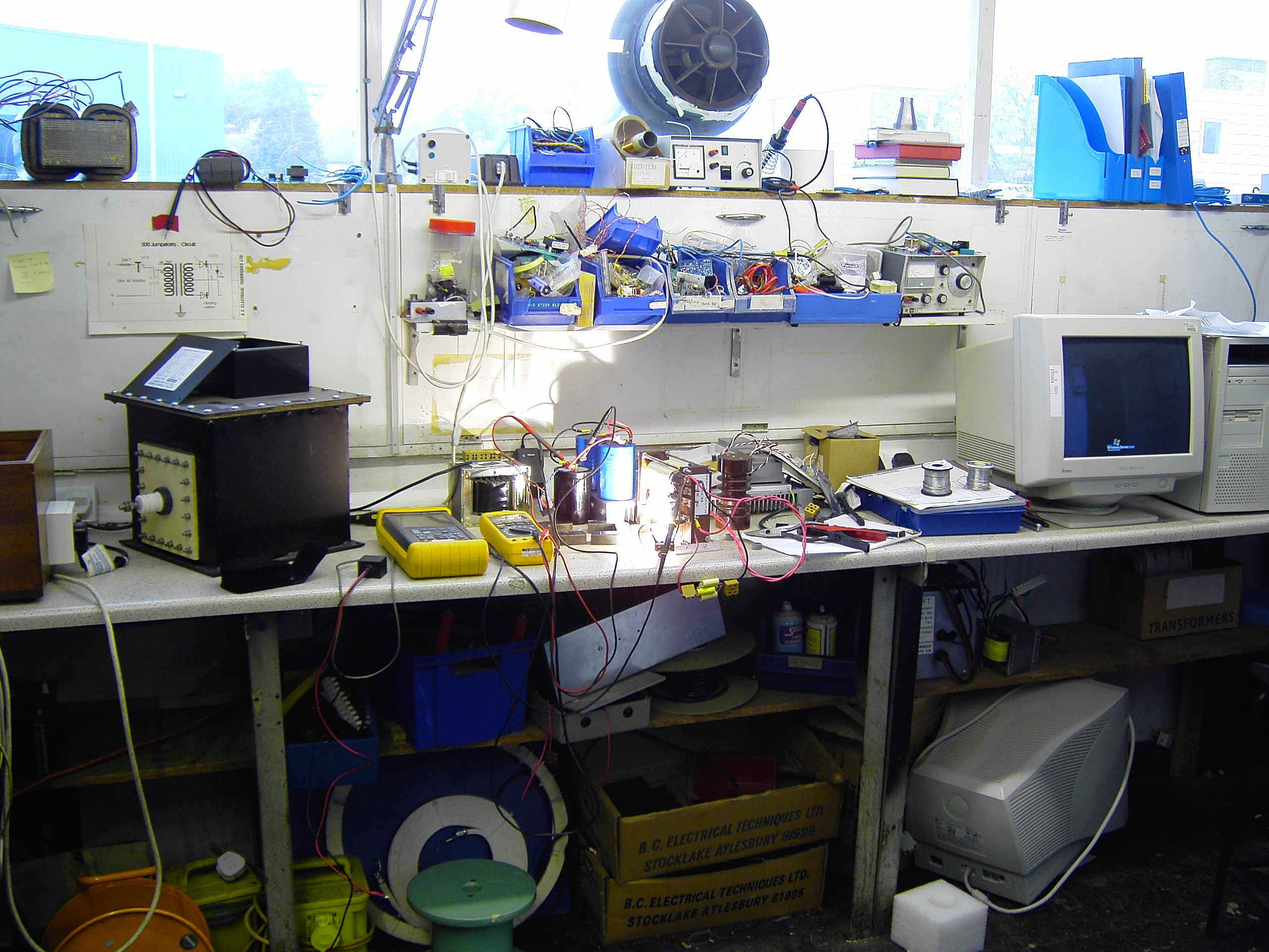
In the above picture the "black box" on the bench is the finished LOPT, much bigger than an average flyback that you would find inside a tv set. hehe. The box contains oil and a lot of measures to prevent arcing to inner case.
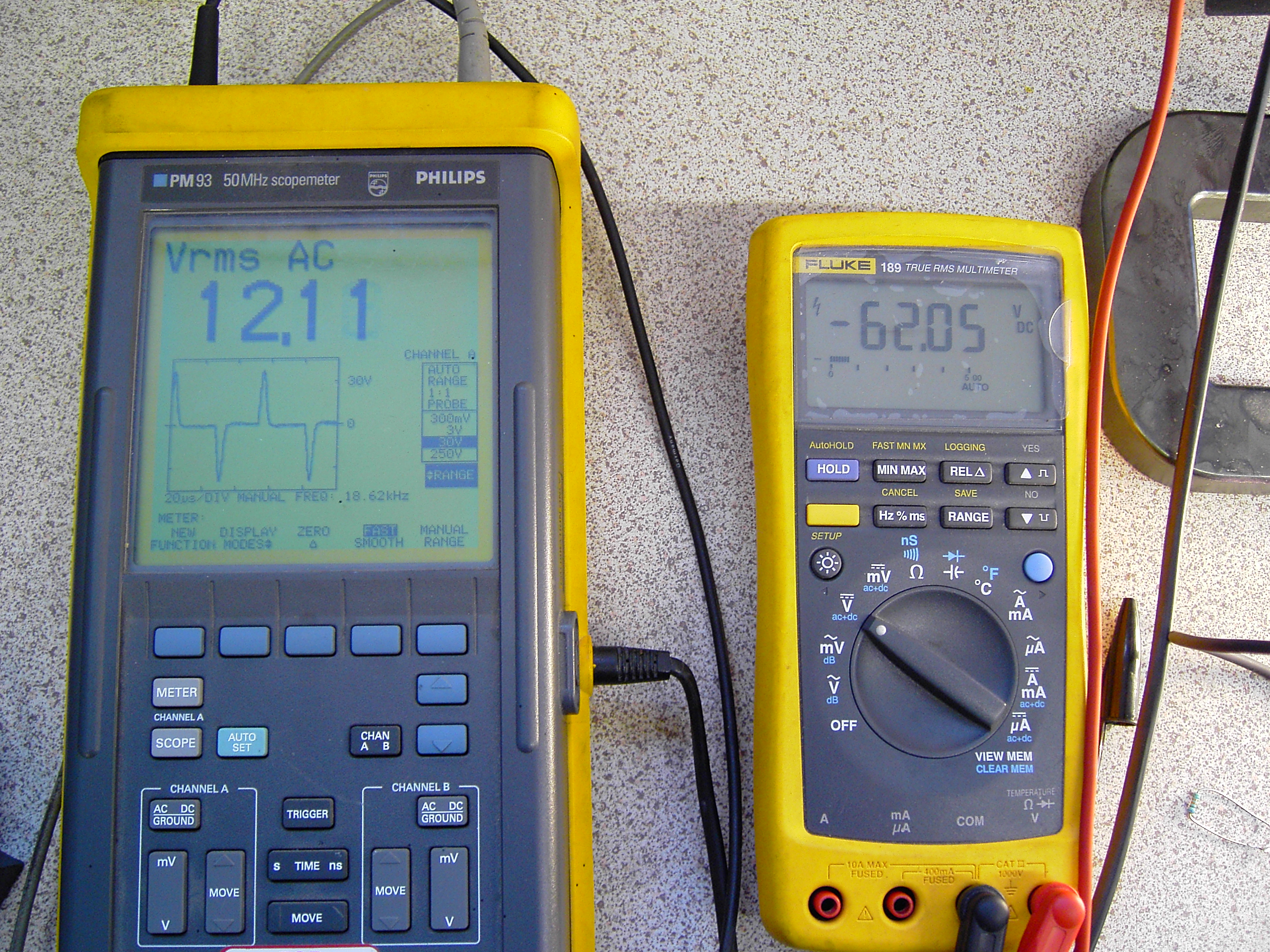
Various meters used for assitaining wether or not bits are live. As you can see the Scope shows the vaveform and voltage across the tuned circuit during testing proceedures. The Fluke 189, is displaying the main capacitor voltage. That would mean that the split capacitors have half the potential of the main capacitor. This is due to the inverter being configured in halfbridge mode for chepness, as the full bridge uses 4 devices. plus more to go wrong and the need for more isolated power supplies for the drive optocouples.
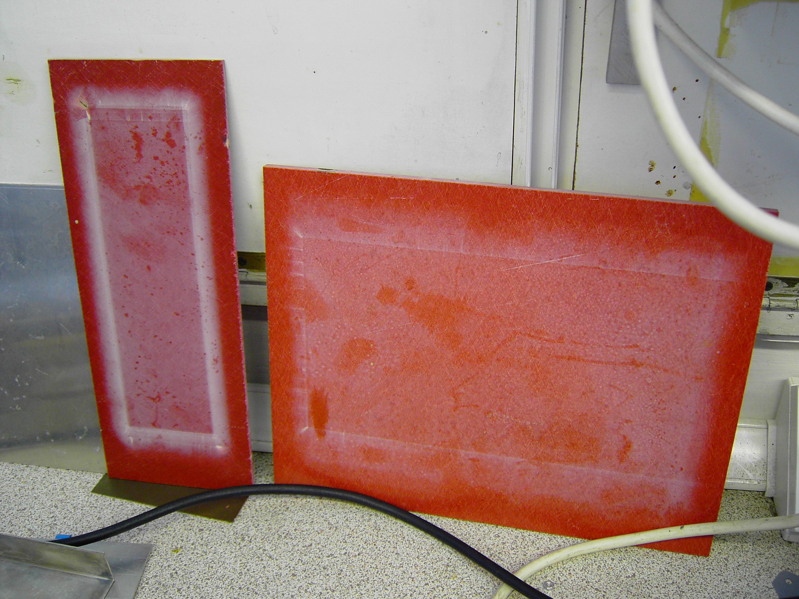
Remains of test plates, used when "firing up" the transformer after tuning and testing. Plates pictured to Left are glass fibre in epoxy resin. The leftmost one is 2.5mm thick and the one to the right is 5mm thick, but used a bigger plate.
The smaller plate grew hotter and eventualy developed a fault top corner, and tracked through the material.