PTO
Construction Method
(Arv - K7HKL)
Credit for my begining to work with the brass screw type PTO should be
given to WA6OTP who builds and sells a PTO Kit. You can see his
product at <http://www.wa6otp.com/pto.htm>. I tried to take
his design a few steps further by adding more stability to the screw
and by providing a convenient front-panel bezel to make it look a bit
more professional. You do not have to make yours exactly like
mine. Make it fit the contents of your junk box and what you can
purchase locally and inexpensively. Use whatever oscillator
circuit you are familiar with, and try to make improvements on both my
and WA6OTP's ideas.
The argument for a screw type PTO is that it provides very slow-motion
tuning without using an expensive speed reduction mechanism, it is
inexpensive to construct, and almost anybody can build
one. The negative aspect of this design is that the tuning knob
will move closer or further from the front panel as the frequency is
changed. This is not usually a problem because 1/2 to 3/4
inch (12 mm to 20 mm) of travel is usually all the tuning that is
needed. With a 32 turns-per-inch screw your tuning would be
spread over 16 turns for 1/2 inch tuning and 24 turns for 3/4 inch
movement. This is usually adequate for all or part of a ham
band. The tuning screw may be as small as 6-32 or much
larger. I have built several that used a section of 1/4 inch
brass threaded rod inside a section of 1/2 inch PVC pipe.
In the design shown below there is no provision for a dial readout of
frequency. For QRP rigs that only tune a narrow slice of a ham
band it is possible to do without this. For more serious use you
can add an inexpensive frequency counter.
See Hans
G0UPL's simple counters at:
<http://www.hanssummers.com/radio/sfreq/index.htm>
<http://www.hanssummers.com/radio/huffpuff/minimalist/3chip/index.htm>
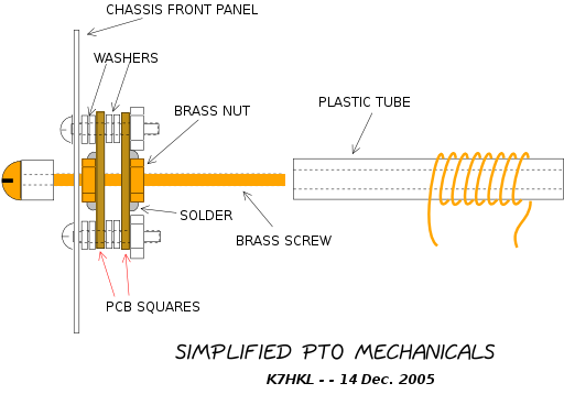
For an 8-32 brass screw the PCB squares will need to be 1 inch on a
side. Fasten the plastic tube to the back of the mounting plate
using hot-melt glue or epoxy. The coil may be slid back and forth
on the form and spread or compressed to get the exact tuning range you
need.
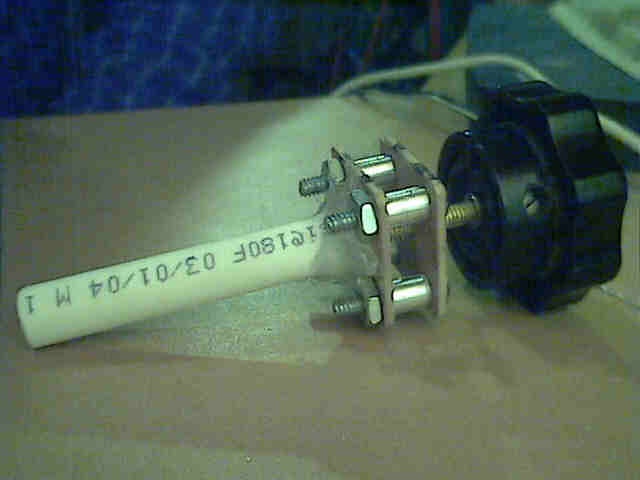
Here is a picture of the mechanism shown in the drawing above:
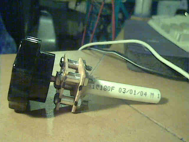
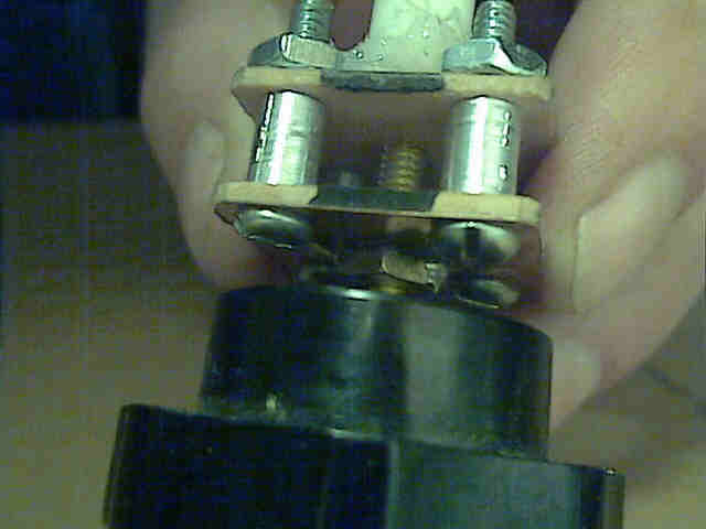
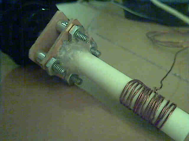
This close-up shows the brass nut solodered to the PCB square
The plastic tube in this case is nylon basin tube (the kind that
connects water to wash basin valves).
It is inexpensive and is 3/8 inch OD and 1/4 inch ID.
The coil may be slid forward or back and expanded or compressed to get
exactly the right tuning range.
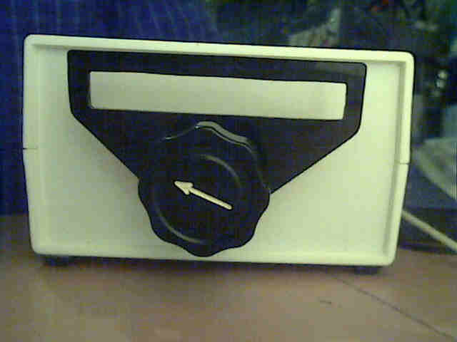
By cutting a plastic bezel for your brass screw PTO you can make it
look quite professional. This one is
intended to have a digital frequency counter behind it for tuning
readout on a direct conversion receiver.
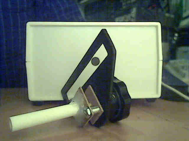
And here is the final product, ready for wiring the rest of the reciver
circuit and listening on my favorite ham band.